00196497-07_SM_SXDX12_en.pdf - 第178页
Service Work Conveyor Conveyor 3.6.7 Stoppers and Sensors 178 Service Manual SIPLACE SX1/SX2/DX1/DX2 FS02 Installation ► Follow the removal in structions in reverse order for installati o n. Also observe the following in…
Service Work Conveyor
3.6.7 Stoppers and Sensors Conveyor
Service Manual SIPLACE SX1/SX2/DX1/DX2 FS02 177
3.6.7.3
3.6.7.3 Replacing the Sonar Sensor PXS240 [03089004Sxx]
Replacing the Sonar Sensor PXS240 [03089004Sxx]
All sonar sensors used can be disconnected for replacement and dismantled.
Parts, equipment and tools
▪ Programming cable for PXS240 sensor [03073330-xx]
▪ Sonar sensor UB100-F77 [03089004Sxx] (compatible)
Incl. 2x "Press-in thread insert M2" [03088352-xx]
(replaces: old: sonar sensor PXS240 [03069863-xx])
▪ Setting gauge for ultrasonic sensors [03076989-xx]
▪ Loctite 401 [00805104-xx], if required
Overview
Removal
► Use the software to move the conveyor sides into the position which allows you best access. Alter-
natively, you can also loosen the conveyor side clamps on the dual conveyor (see "3.6.1 Loosening
the Conveyor Side Clamps" [ ➙ 143]).
► Switch off the machine, disconnect it from the power supply and secure it to prevent unauthorized
reactivation. Observe the instructions in section "1.2 Preparatory Work..." [ ➙ 13].
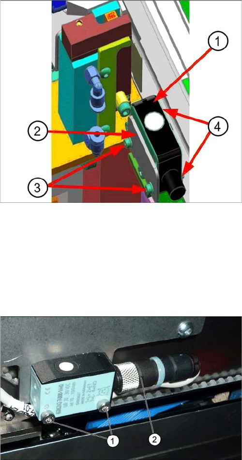
Sonar sensor on the stopper positions:
1. Sonar sensor
2. Sensor rail fixture bracket
3. Fastening screws ISO4762–M2x16-A2-70
[03042529-xx] with washers DIN125-A2.2-140HV-A2
[00301541-xx].
4. Press-in nuts
► Dismantle any cover which is on the sonar sensor.
► Loosen the screws (1) fastening the ultrasonic sen-
sors.
► Unscrew the press-fit connection (2) from the ultra-
sonic sensor and remove the ultrasonic sensor from
the machine.
Service Work Conveyor
Conveyor 3.6.7 Stoppers and Sensors
178 Service Manual SIPLACE SX1/SX2/DX1/DX2 FS02
Installation
► Follow the removal instructions in reverse order for installation. Also observe the following instruc-
tions:
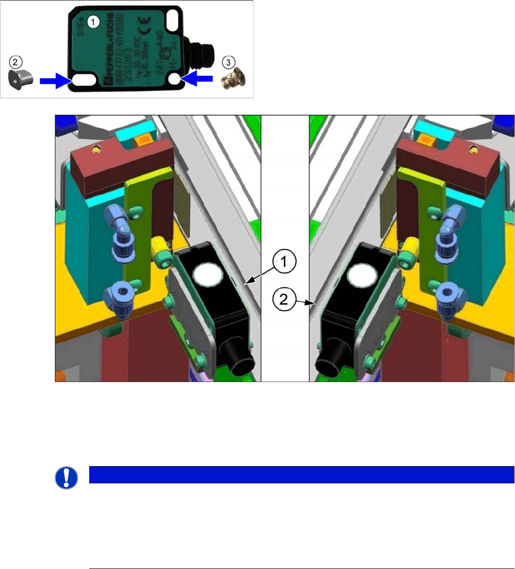
► Insert the sockets into the sensor:
1. For sonar sensors on the sensor rail of the right side, you need to position the sockets on the right,
as viewed from the connection side.
2. For sonar sensors on the sensor rail of the left side, you need to position the sockets on the left, as
viewed from the connection side.
► Perform a function check. If this is not successful, you will need to reteach the sonar sensor (see
"4.6.2 Teaching the Sonar Sensor" [ ➙ 278]).
1. Sonar sensor
2. Threaded socket P+F [03096703-xx] (oval)
3. Press-in threaded insert M2 [03088352-xx] (round)
NOTICE
Recommendation: fix socket with adhesive
The sockets do not need to be fixed with adhesive for technical reasons. However, for easier
assembly it may be advisable to fix them like this. This helps to prevent them from falling out or
from the socket being turned with other parts.
► Use a suitable adhesive for fixing. It should be designed to bind plastics with metal (e.g.
Loctite 401 [00805104-xx]).
Service Work Conveyor
3.6.7 Stoppers and Sensors Conveyor
Service Manual SIPLACE SX1/SX2/DX1/DX2 FS02 179
3.6.7.4
3.6.7.4 Replacing the Solenoid Valve (Sensor Rail) [03089866-xx]
Replacing the Solenoid Valve (Sensor Rail) [03089866-xx]
Parts, equipment and tools
▪ Solenoid valve 5/2-micro-way valve 518 [03089866-xx]
Overview
Removal
► Switch off the machine, disconnect it from the power supply and secure it to prevent unauthorized
reactivation. Observe the instructions in section "1.2 Preparatory Work..." [ ➙ 13].
► Dismantle the sensor rail cover plate over the relevant solenoid valve.
► Unplug the solenoid valve from all electrical and pneumatic connections. You may want to mark the
positions of these connections, to make clear assignment easier later on.
► Loosen the two screws fastening the solenoid valve.
Installation
► Follow the removal instructions in reverse order for installation.
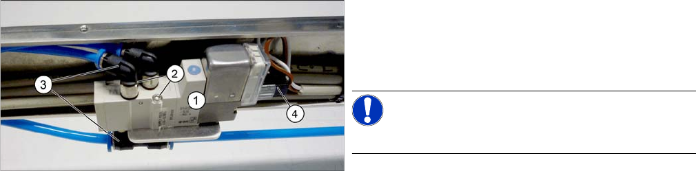
1. Solenoid valve
2. Screws fastening the solenoid valve
3. Compressed air connections
4. Electrical connection
NOTICE!
You do not need to dismantle the sensor rail!