00196497-07_SM_SXDX12_en.pdf - 第187页
Service Work Conveyor 3.7.3 Replacing the Tension Spring [03010352-xx] Component Troll ey SX Service Manual SIPLACE SX1/SX2/DX1/DX2 FS02 187 3.7.3 3 . 7 . 3 R e p la c in g t h e T e n s io n S p r in g [ 0 3 0 1 0 3 5 2…
Service Work Conveyor
Component Trolley SX 3.7.2 Replacing the Insert Feeder [03002898-xx]
186 Service Manual SIPLACE SX1/SX2/DX1/DX2 FS02
3.7.2
3.7.2 Replacing the Insert Feeder [03002898-xx]
Replacing the Insert Feeder [03002898-xx]
Parts, equipment and tools
Select the right insert feeder:
Removal
► Move the component trolley out of the machine.
► Loosen the screw fastening the guide profile and remove the guide profile.
Installation
► Follow the removal instructions in reverse order for installation. Also observe the following instruc-
tions:
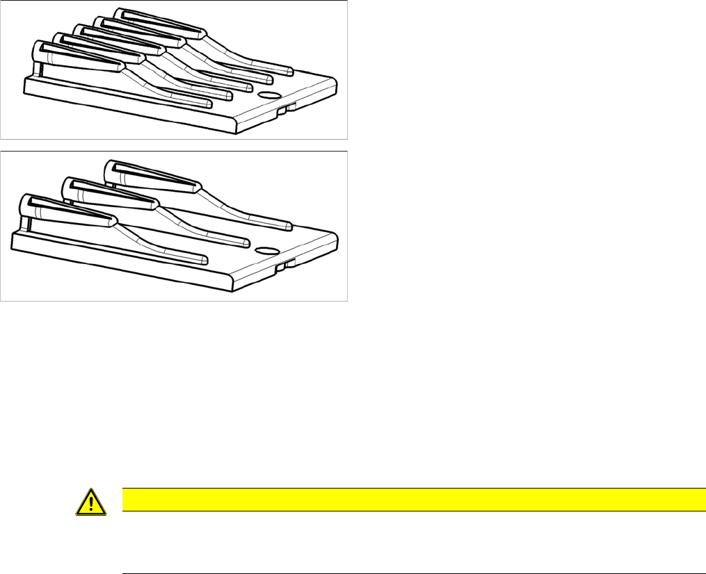
Insert feeder [03002898-xx]
Suitable for:
▪ X-Series component trolley
▪ Component trolley SX1/SX2 (30 or 60 tracks)
▪ Manual table X-Series S
Insert feeder [03085635-xx]
Suitable for:
▪ Manual table DX series
CAUTION
Installation instructions
► Make sure that the insert is aligned properly with the guidance behind it. You must be able
to push feeder modules into the feeder location without edge interference.
Service Work Conveyor
3.7.3 Replacing the Tension Spring [03010352-xx] Component Trolley SX
Service Manual SIPLACE SX1/SX2/DX1/DX2 FS02 187
3.7.3
3.7.3 Replacing the Tension Spring [03010352-xx]
Replacing the Tension Spring [03010352-xx]
Parts, Equipment and Tools
▪ Tension spring d=0.63* D=5.6* Lo=23.3 [03010352-xx]
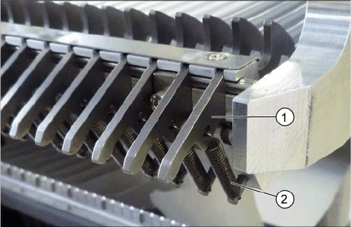
Overview
Removal
► Move the component trolley out of the machine.
► Unhook the tension spring.
Installation
► Follow the removal instructions in reverse order for installation.
1. Locking latch
2. Tension spring
Service Work Conveyor
Component Trolley SX 3.7.4 Replacing the Locking Latch [03069205-xx]
188 Service Manual SIPLACE SX1/SX2/DX1/DX2 FS02
3.7.4
3.7.4 Replacing the Locking Latch [03069205-xx]
Replacing the Locking Latch [03069205-xx]
Parts, equipment and tools
▪ Single locking latch [03069205-xx]
Overview
Preparation
► Move the component trolley out of the machine.
► Remove the waste tape container and empty it, before inserting it again. This makes sure that any
parts which fall down are not lost.
Removal
► Loosen the 3 screws fastening the cover. Use a suitable Phillips screwdriver, to avoid damaging the
screws.
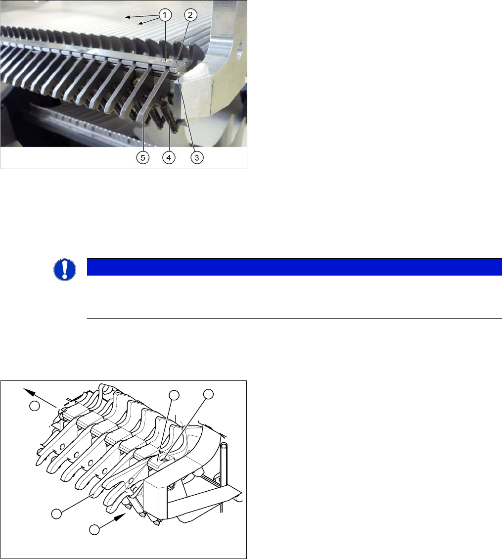
1. 3x fastening screws for the cover
2. Cover plate for locking strip
SX1/SX2: [03053248-xx]
X/SX4: [03077142-xx]
3. Shaft
4. Tension spring
5. Locking latch
NOTICE
Tape waste container
You can use the waste tape container as a surface on which to place small parts e.g. tension
springs, locking latches etc.
► Unhook all tension springs (1) from the locking latch-
es (2).
► Loosen the screws (3) fastening the pressure plates
(4).
► Pull out the locking latches with the shaft (5).
► The locking latches can now be pushed off the shaft.
4
5
1
3
2