00196497-07_SM_SXDX12_en.pdf - 第191页
Service Work Conveyor 3.8.1 Replacing the FCU Docking Station for SX Compo nent Trolley Service Manual SIPLACE SX1/SX2/DX1/DX2 FS02 191 3.8 3 . 8 D o c k in g S t a t io n f o r S X C o m p o n e n t T r o lle y Docking …
Service Work Conveyor
Component Trolley SX 3.7.6 Replacing the Circuit Breaker Actuator (Schmersal) [03110183-xx]
190 Service Manual SIPLACE SX1/SX2/DX1/DX2 FS02
3.7.6
3.7.6 Replacing the Circuit Breaker Actuator (Schmersal) [03110183-xx]
Replacing the Circuit Breaker Actuator (Schmersal) [03110183-xx]
Parts, Equipment and Tools
▪ SPP Circuit Breaker Actuator COT 60 [03110183-xx]
(including rubber straps and bushings)
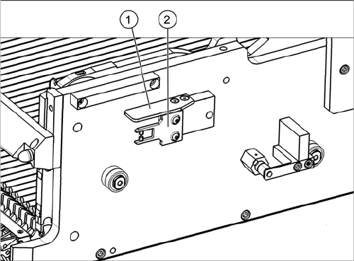
Overview
Removal/Installation
► Remove the fastening screws of the actuator and the protective plate and lift these off.
► Fit the new actuator together with the new rubber straps and bushings. Tighten the two fastening
screws hand-tight.
► Fix the protective cover with two fastening screws.
1. Protective plate
2. Actuator
Service Work Conveyor
3.8.1 Replacing the FCU Docking Station for SX Component Trolley
Service Manual SIPLACE SX1/SX2/DX1/DX2 FS02 191
3.8
3.8 Docking Station for SX Component Trolley
Docking Station for SX Component Trolley
3.8.1
3.8.1 Replacing the FCU
Replacing the FCU
Replacing the FCU follows the same procedure as replacing the FCU at the COT insert. For more infor-
mation about this, read section "3.10.5 Replacing the Feeder Control Unit (FCU) [03059666-xx]"
[ ➙ 217].
3.8.2
3.8.2 Replacing the Feeder Unlocking Device
Replacing the Feeder Unlocking Device
Replacing the feeder unlocking device follows the same procedure as replacing the feeder unlocking de-
vice at the COT insert. For more information about this, read section "3.10.3 Replacing the Feeder Un-
locking Device 60-fold [03057772-xx]" [ ➙ 215].
See also
3.10.1 Replacing the Unlocking Pins [03088220-xx] [ ➙ 206]
3.8.3
3.8.3 Replacing the Power Supply
Replacing the Power Supply
For replacing the power supply, read the Technical Information "Power supply for the docking station for
the SIPLACE X component cart [116933] and SIPLACE SX component cart [116965] has been with-
drawn" [DE: TI2015-04D07] [EN: TI2015-04E07].
Service Work Conveyor
Manual table 3.9.1 Replacing the Guide Profile (Omega Profile)
192 Service Manual SIPLACE SX1/SX2/DX1/DX2 FS02
3.9
3.9 Manual table
Manual table
See also
3.10.8 Upgrade Kit COT-I-30 CAN Switch for 2nd WPC [03085518-xx] [ ➙ 220]
3.9.1
3.9.1 Replacing the Guide Profile (Omega Profile)
Replacing the Guide Profile (Omega Profile)
Parts, equipment and tools
▪ Guide profile on front section: guide profile L=150 mm [03081674-xx]
▪ Guide profile on back section: guide profile L=280 mm [03084321-xx]
Overview
Removal
► Loosen the screws fastening the guide profile on the underside of the table.
► Remove the guide profile.
Installation
► Follow the removal instructions in reverse order for installation. Also observe the following instruc-
tions:
CAUTION
Back part, dummy feeder
Do not operate the machine without the back part of the manual table or without the dummy
feeder.
NOTICE
Always replace together
We recommend that you always replace the guide profiles which belong together (on the front
and back parts) at the same time.
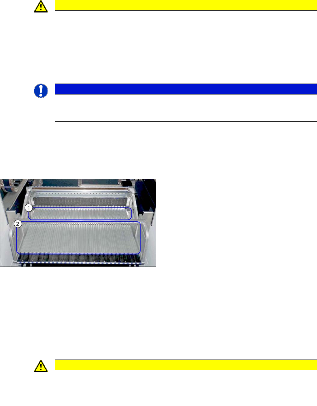
Guide profiles (using example of DX1/DX2)
1. Guide profiles on the front section
2. Guide profiles on the back section
CAUTION
Installation instructions
► To correctly align the guide profiles from the front to the back part (removable), we recom-
mend proceeding as follows:
Place a feeder to the left and right of the guide profile and then screw the guide profiles tight.