00196497-07_SM_SXDX12_en.pdf - 第199页
Service Work Conveyor 3.9.6 Replacing the Centering Bar Manual table Service Manual SIPLACE SX1/SX2/DX1/DX2 FS02 199 3.9.6 3 . 9 . 6 R e p la c in g t h e C e n t e r in g B a r Replacing the Centering Bar Parts, equipme…
Service Work Conveyor
Manual table 3.9.5 Replacing the Feeder Control Unit (FCU)
198 Service Manual SIPLACE SX1/SX2/DX1/DX2 FS02
3.9.5.1
3.9.5.1 Operating the Unlocking Hook
Operating the Unlocking Hook
Parts, equipment and tools
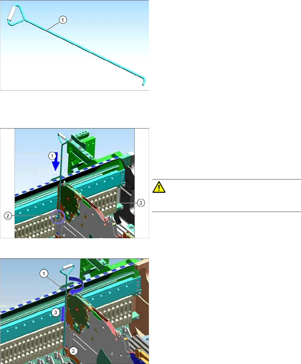
▪ Unlocking hook [03038882-xx]
Overview
Application
Unlocking hook for manual tables
In the event of an error, it is not possible to remove the X
feeders manually by just removing the table.
If the Feeder Control Unit (FCU) fails, the unlocking hook
can be used to manually remove the X feeders from the
table. You can then replace the FCU.
The unlocking hook is supplied in the service box with
each machine order.
1. Red marking - height mark to used tape chute, for un-
locking the feeder.
Guidance for unlocking hook
Once the manual table has been fully configured with
feeders, start to remove the feeders with the unlocking
hook. Start at track 1.
► (1) Guide the unlocking hook downwards, between
the side wall of the table and the feeder at track 1, lev-
el with the feeder pickup window.
CAUTION!
Make sure that the tip of the hook (2) points to the FCU
(3).
Feeder unlocking device
► If the red mark (1) on the unlocking hook is at the
same height as the upper edge of the used tape
chute, turn the hook by 90 degrees. The hook must
then engage between the feeder and the latch on the
table (2).
► Press the unlocking hook down more (3) and remove
the feeder.
► Repeat these steps for all other feeders.
Service Work Conveyor
3.9.6 Replacing the Centering Bar Manual table
Service Manual SIPLACE SX1/SX2/DX1/DX2 FS02 199
3.9.6
3.9.6 Replacing the Centering Bar
Replacing the Centering Bar
Parts, equipment and tools
Select the correct spare part:
Overview
Removal
► Loosen the four fastening screws on the front side.
► Pull the centering bar off the locating pins.
Installation
► Follow the removal instructions in reverse order for installation. Also observe the following instruc-
tions:
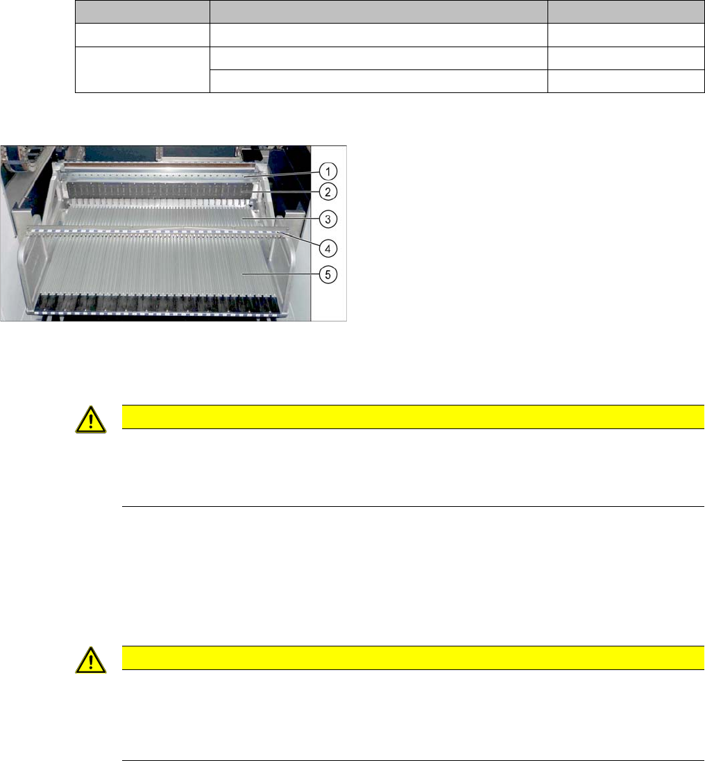
Machine type Designation Item No.
DX4 Stop rail 40/2-fold 03082777-xx
DX1/DX2 Stop rail 60/2-fold 03081975-xx
Stop rail 30/2-fold 03082572-xx
Manual table (using example of DX1/DX2)
1. Centering bar
2. FCU
3. Front part
4. Back part
CAUTION
Front and back section must be fitted
The centering bar may only be released if both the front and back sections are fixed inside the
machine. The table could be distorted otherwise. The possible consequence would be prob-
lems with feeder recognition.
CAUTION
Installation instructions
► Before installation, clean the centering pins on the sides of the centering bar.
► Make sure that the centering bar is not tensioned.
► Check that all feeders fit easily into the centering and are not subjected to tension.
Service Work Conveyor
Manual table 3.9.7 Replacing the Complete Mounting Frame
200 Service Manual SIPLACE SX1/SX2/DX1/DX2 FS02
3.9.7
3.9.7 Replacing the Complete Mounting Frame
Replacing the Complete Mounting Frame
Parts, equipment and tools
Select the right mounting frame:
▪ Rubber mallet
Overview
Removal
► Dismantle the back section of the manual table. (See "3.9.2 Removing the Back Section of the Man-
ual Table" [ ➙ 193])
Machine type Designation Item No.
DX4 COT insert MT 40 03082689-xx
DX1/DX2 COT insert MT 60 03081574-xx
COT insert MT 30 03082560-xx
Manual table (using example of DX1/DX2)
1. Centering bar
2. FCU
3. Front part
4. Back part
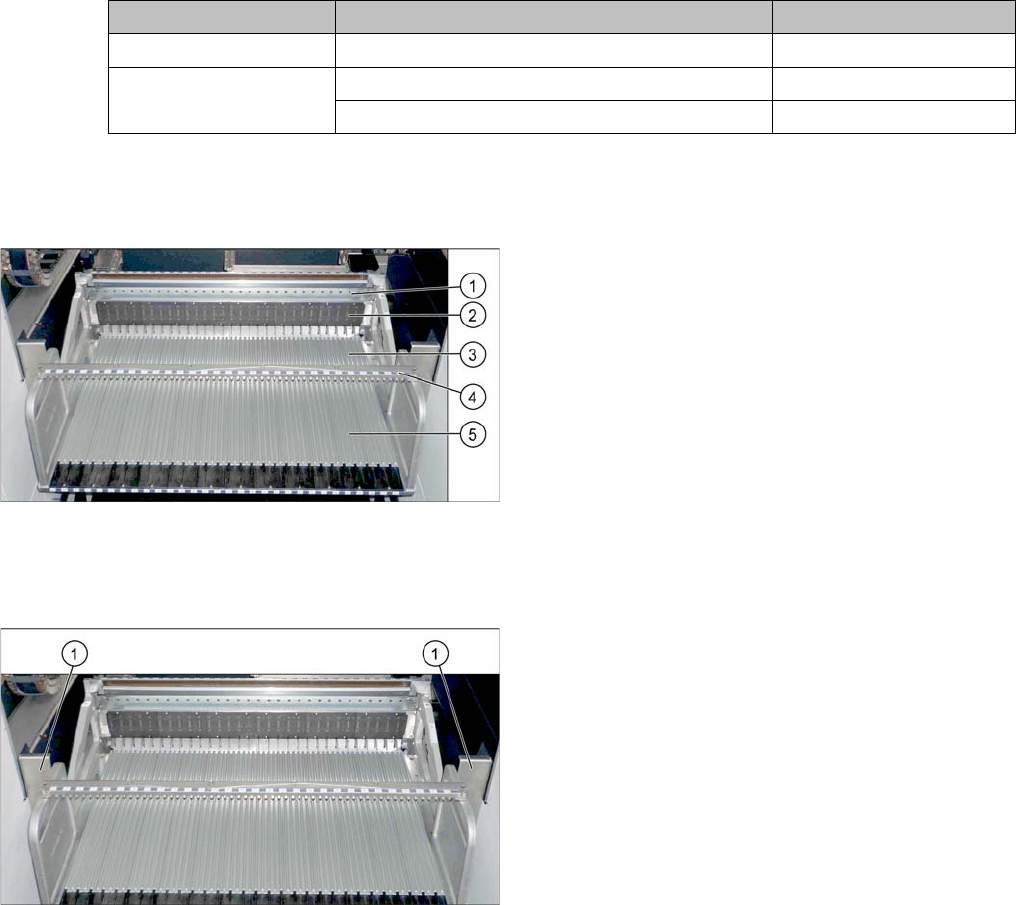
► For better access, dismantle the two protective
plates (1) on the side of the mounting frame.