00196497-07_SM_SXDX12_en.pdf - 第201页
Service Work Conveyor 3.9.7 Replacing the Complete Mounting Frame Manual table Service Manual SIPLACE SX1/SX2/DX1/DX2 FS02 201 ► Dismantle the cut ter. (See th e se ction about th e cutter) Installation ► Follow the remo…
Service Work Conveyor
Manual table 3.9.7 Replacing the Complete Mounting Frame
200 Service Manual SIPLACE SX1/SX2/DX1/DX2 FS02
3.9.7
3.9.7 Replacing the Complete Mounting Frame
Replacing the Complete Mounting Frame
Parts, equipment and tools
Select the right mounting frame:
▪ Rubber mallet
Overview
Removal
► Dismantle the back section of the manual table. (See "3.9.2 Removing the Back Section of the Man-
ual Table" [ ➙ 193])
Machine type Designation Item No.
DX4 COT insert MT 40 03082689-xx
DX1/DX2 COT insert MT 60 03081574-xx
COT insert MT 30 03082560-xx
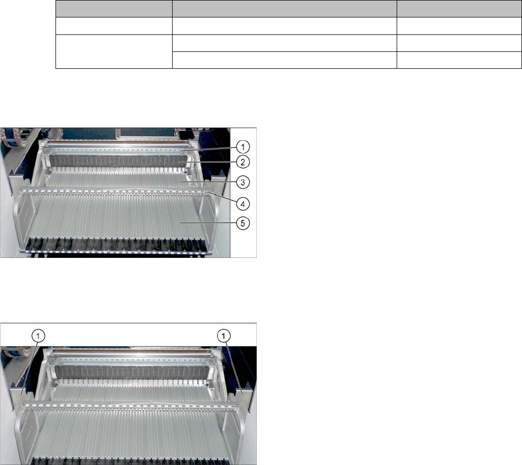
Manual table (using example of DX1/DX2)
1. Centering bar
2. FCU
3. Front part
4. Back part
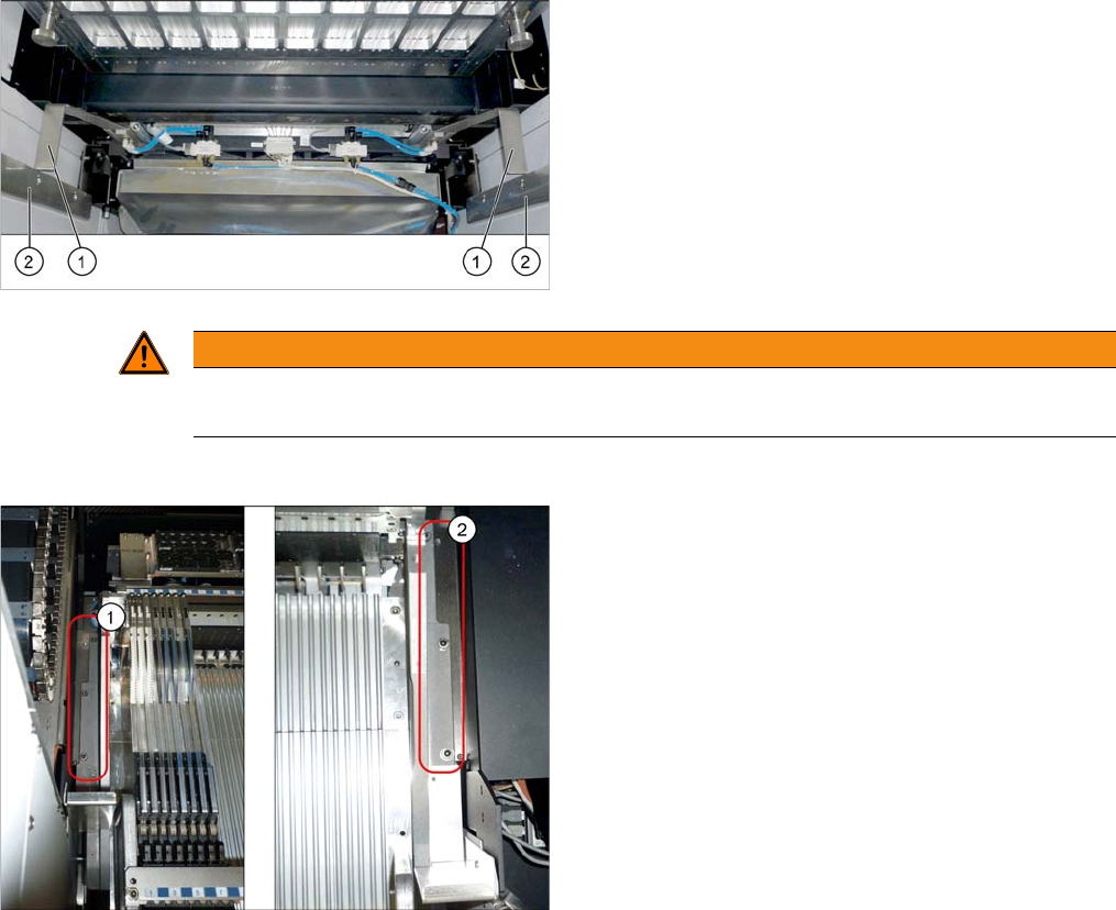
► For better access, dismantle the two protective
plates (1) on the side of the mounting frame.
Service Work Conveyor
3.9.7 Replacing the Complete Mounting Frame Manual table
Service Manual SIPLACE SX1/SX2/DX1/DX2 FS02 201
► Dismantle the cutter. (See the section about the cutter)
Installation
► Follow the removal instructions in reverse order for installation.
See also
3.10.5 Replacing the Feeder Control Unit (FCU) [03059666-xx] [ ➙ 217]
3.9.3 Removing the Front Section of the Manual Table [ ➙ 194]
► Dismantle the stoppers (1).
You may need to lower the cutter onto the support
plates (2). (See "3.11.1 Replacing the Cutter
[03063781Sxx]" [ ➙ 223])
WARNING
Do not remove the front part
Do not dismantle the front section here as the frame would otherwise be unstable.
► Loosen the fastening screws on the left (1) and
right (2) and remove the mounting frame.
Service Work Conveyor
Manual table 3.9.8 Replacing the Feeder Lock on the Manual Table [03082778-xx]
202 Service Manual SIPLACE SX1/SX2/DX1/DX2 FS02
3.9.8
3.9.8 Replacing the Feeder Lock on the Manual Table [03082778-xx]
Replacing the Feeder Lock on the Manual Table [03082778-xx]
Please also observe section Replacing the Locking Latch [03069205-xx].
Parts, equipment and tools
Select the correct spare part:
▪ Rubber mallet
Overview
Removal
Machine type Designation Item No.
X-Series S Feeder lock/X-Series (1x) 03023777-xx
SX1/SX2, DX1/DX2 Feeder lock 30/2-fold
(1x per 30 track manual table or component trolley)
(2x per 60 track manual table or component trolley)
03081586-xx
DX4 Feeder lock 40-fold
(1x per manual table or component trolley)
03082778-xx
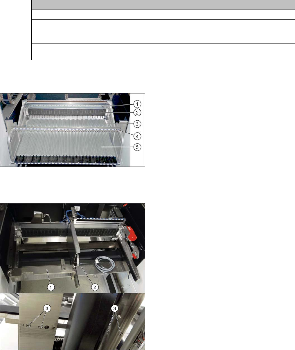
Manual table (using example of DX1/DX2)
1. Centering bar
2. FCU
3. Front section with feeder lock (with locking latches)
4. Fixture bar
5. Back part
If there is a WPC at the same location, perform the follow-
ing two steps as well:
► Dismantle the WPC docking rail (1).
► Dismantle the left side of the insert mechanism (2).
Loosen the 4 fastening screws (3) on the underside
and the 2 fastening screws on the top of the empty
tape duct.