00196497-07_SM_SXDX12_en.pdf - 第202页
Service Work Conveyor Manual table 3.9.8 Replacing the Feeder Lock on the Manual Table [03082778-xx] 202 Service Manual SIPLACE SX1/SX2/DX1/DX2 FS02 3.9.8 3 . 9 . 8 R e p la c in g t h e F e e d e r L o c k o n t h e M a…
Service Work Conveyor
3.9.7 Replacing the Complete Mounting Frame Manual table
Service Manual SIPLACE SX1/SX2/DX1/DX2 FS02 201
► Dismantle the cutter. (See the section about the cutter)
Installation
► Follow the removal instructions in reverse order for installation.
See also
3.10.5 Replacing the Feeder Control Unit (FCU) [03059666-xx] [ ➙ 217]
3.9.3 Removing the Front Section of the Manual Table [ ➙ 194]
► Dismantle the stoppers (1).
You may need to lower the cutter onto the support
plates (2). (See "3.11.1 Replacing the Cutter
[03063781Sxx]" [ ➙ 223])
WARNING
Do not remove the front part
Do not dismantle the front section here as the frame would otherwise be unstable.
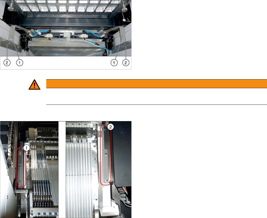
► Loosen the fastening screws on the left (1) and
right (2) and remove the mounting frame.
Service Work Conveyor
Manual table 3.9.8 Replacing the Feeder Lock on the Manual Table [03082778-xx]
202 Service Manual SIPLACE SX1/SX2/DX1/DX2 FS02
3.9.8
3.9.8 Replacing the Feeder Lock on the Manual Table [03082778-xx]
Replacing the Feeder Lock on the Manual Table [03082778-xx]
Please also observe section Replacing the Locking Latch [03069205-xx].
Parts, equipment and tools
Select the correct spare part:
▪ Rubber mallet
Overview
Removal
Machine type Designation Item No.
X-Series S Feeder lock/X-Series (1x) 03023777-xx
SX1/SX2, DX1/DX2 Feeder lock 30/2-fold
(1x per 30 track manual table or component trolley)
(2x per 60 track manual table or component trolley)
03081586-xx
DX4 Feeder lock 40-fold
(1x per manual table or component trolley)
03082778-xx
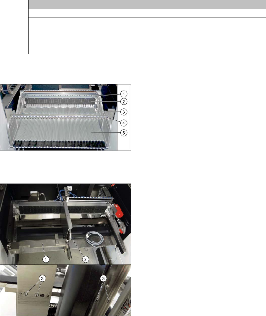
Manual table (using example of DX1/DX2)
1. Centering bar
2. FCU
3. Front section with feeder lock (with locking latches)
4. Fixture bar
5. Back part
If there is a WPC at the same location, perform the follow-
ing two steps as well:
► Dismantle the WPC docking rail (1).
► Dismantle the left side of the insert mechanism (2).
Loosen the 4 fastening screws (3) on the underside
and the 2 fastening screws on the top of the empty
tape duct.
Service Work Conveyor
3.9.9 Replacing the Used Tape Chute Manual table
Service Manual SIPLACE SX1/SX2/DX1/DX2 FS02 203
► Further removal and installation of the feeder lock is the same as that for the front section of the man-
ual table. For more information about this, read section "3.9.3 Removing the Front Section of the
Manual Table" [ ➙ 194].
Installation
► Follow the removal instructions in reverse order for installation.
See also
3.9.2 Removing the Back Section of the Manual Table [ ➙ 193]
3.9.9
3.9.9 Replacing the Used Tape Chute
Replacing the Used Tape Chute
Parts, Equipment and Tools
Select the correct spare part:
Removal
► Switch off the machine, disconnect it from the power supply and secure it to prevent unauthorized
reactivation. Observe the instructions in section "1.2 Preparatory Work..." [ ➙ 13].
Component Supply - Manual Tables - Dismantling Protections - Color Version
► Loosen the two screws fastening the used tape chute fixtures. There are one screw on the left and
one on the right of the used tape chute.
► Remove the screws fastening the used tape chute.
► Take the used tape chute down and out of the machine.
Machine type Designation Item No.
DX1/DX2 Used tape chute 60 tracks 03064026-xx
Used tape chute 30 tracks 03073312-xx
If required, secure used tape chute DX1/DX2 left 03094519-xx
If required, secure used tape chute DX1/DX2 right 03094522-xx
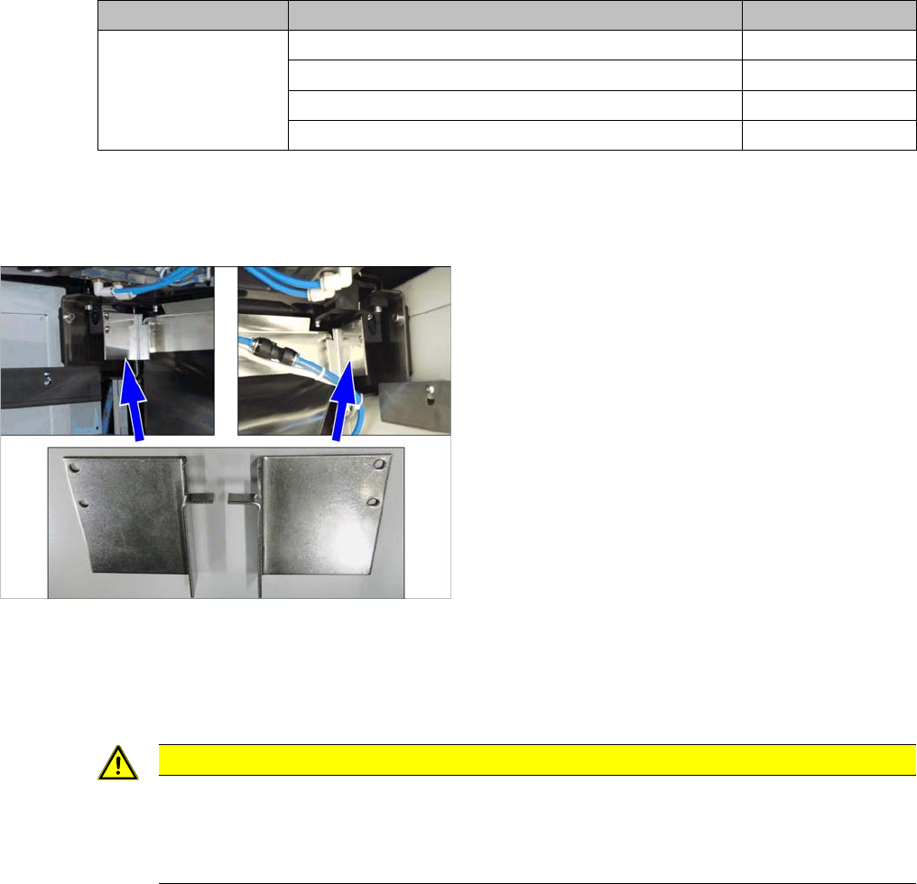
Manual tables only:
► Dismantle the protections:
– Protection waste chute DX1/2 left [03094519-xx]
– Protection waste chute DX1/2 right [03094522-
xx]
CAUTION
Risk of cutting
The cutter is located under the tape channel. The blades there have very sharp edges.
► Do not reach into the cutter and make sure that it is never freely accessible for longer peri-
ods or without supervision.