00196497-07_SM_SXDX12_en.pdf - 第207页
Service Work Conveyor 3.10.2 Replacing the SX1/SX2 Component Trolley Feed Device Asse mbly [03059353-xx] COT insert Service Manual SIPLACE SX1/SX2/DX1/DX2 FS02 207 Installation ► Follow the removal in structions in rever…
Service Work Conveyor
COT insert 3.10.1 Replacing the Unlocking Pins [03088220-xx]
206 Service Manual SIPLACE SX1/SX2/DX1/DX2 FS02
3.10
3.10 COT insert
COT insert
Fragmen t for DX12
3.10.1
3.10.1 Replacing the Unlocking Pins [03088220-xx]
Replacing the Unlocking Pins [03088220-xx]
Parts, Equipment and Tools
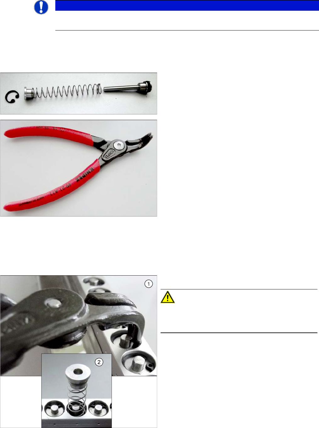
▪ Snipe nose pliers [00353833-xx]
Removal
► Dismantle the feeder unlocking device. (See "3.10.3 Replacing the Feeder Unlocking Device 60-fold
[03057772-xx]" [ ➙ 215])
NOTICE
SX- and DX-Series
Unless specified otherwise, all specifications apply to both the SX and DX Series.
▪ SPP feeder unlock device [03088220-xx]
▪ Inside circlip pliers, bent tips J01 [00365186-xx]
► Use the circlip pliers to remove the circlip.
CAUTION!
Under the circlip you will find a spring (2).
Make sure that the circlip and the upper guidance bush-
ing do not blow away and get lost.
Service Work Conveyor
3.10.2 Replacing the SX1/SX2 Component Trolley Feed Device Assembly [03059353-xx] COT insert
Service Manual SIPLACE SX1/SX2/DX1/DX2 FS02 207
Installation
► Follow the removal instructions in reverse order for installation.
3.10.2
3.10.2 Replacing the SX1/SX2 Component Trolley Feed Device Assembly [03059353-xx]
Replacing the SX1/SX2 Component Trolley Feed Device Assembly [03059353-xx]
Parts, Equipment and Tools
▪ Standard: COT insert for SX1/SX2 [03059353-xx] or
With WPC: COT insert 30 [03082560-xx]
▪ Fit-up aid [03072615-xx]
▪ Suitable lifting device (e.g. Flexolift 175 [03072616-xx])
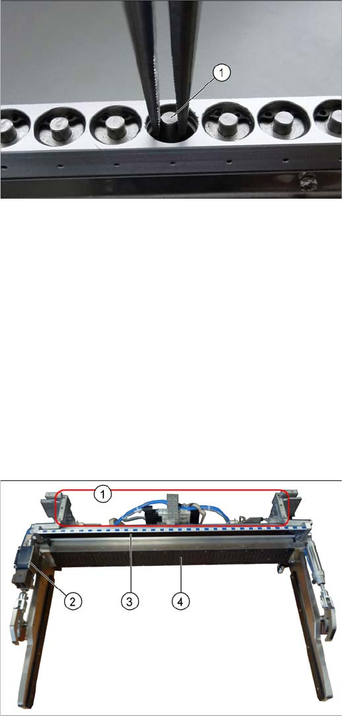
Overview
Removal
► Switch off the machine and secure it to prevent unauthorized reactivation. Observe the instructions
in section "1.2 Preparatory Work..." [ ➙ 13].
► Unplug all connection cables and hoses on the nozzle changer. You may want to mark their posi-
tions, to make clear assignment easier later on.
► Dismantle the nozzle changer.
► Dismantle the cutter (see "3.11.1 Replacing the Cutter [03063781Sxx]" [ ➙ 223]).
► Dismantle the downholder (see also "3.10.2.1 Fitting the Downholder" [ ➙ 209]).
► Unplug all connection cables and hoses for the insert. These are in sectors 2 and 4, on the right of
the location. You may want to mark their positions, to make clear assignment easier later on.
► Use the snipe pliers to remove the unlocking pin.
1. Assembly positions for the nozzle changers
2. Safety Switch for the Component Trolley
3. Empty tape duct
4. Feeder control unit (FCU)
Service Work Conveyor
COT insert 3.10.2 Replacing the SX1/SX2 Component Trolley Feed Device Assembly
208 Service Manual SIPLACE SX1/SX2/DX1/DX2 FS02
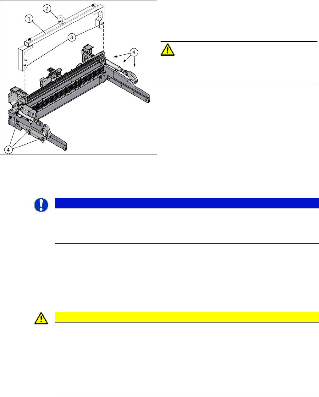
► Attach the fit-up aid to the fixtures provided on the COT insert.
► Remove the six screws fastening the COT insert.
► Fix the lifting device to the eyelet of the fit-up aid.
► Lift the complete COT insert out of the machine and place it on a suitable surface (e. g. four wooden
blocks).
Make sure not to damage any valves, connection cables, hoses, etc.
Installation
► Follow the removal instructions in reverse order for installation. Also observe the following instruc-
tions:
See also
4.5.1 Setting the Nozzle Changer Height (DLM, C&P20, CPP, TH) [ ➙ 271]
1. Fit-up aid
2. Eyelet
3. Fastening screws for fit-up aid
4. Fastening screws for COT insert
CAUTION!
Heavy machine part!
The COT insert is heavy. To lift it out, you will need to use
the fit-up aid and a suitable lifting device.
NOTICE
Marking the installation position
The COT insert can be installed at different positions (inner/outer) in the machine location. Mark
the position of your COT insert, to ensure that this is subsequently returned to its original posi-
tion.
CAUTION
Installation instructions
► Attach the fit-up aid to the new COT insert and lift it into the machine, with the help of the
lifting device.
► Make sure not to damage the cables and hoses.
► Observe the instructions in section "3.10.2.1 Fitting the Downholder" [ ➙ 209].
► Hook the waste tape chute into place. Please also observe section "3.10.10 Replacing the
Waste Tape Chute" [ ➙ 221]. Pay particular attention to the plastic strips and the fuses (if
present).