00196497-07_SM_SXDX12_en.pdf - 第209页
Service Work Conveyor 3.10.2 Replacing the SX1/SX2 Component Trolley Feed Device Asse mbly [03059353-xx] COT insert Service Manual SIPLACE SX1/SX2/DX1/DX2 FS02 209 3.10.2.1 3 . 1 0 . 2 . 1 F it t in g t h e D o w n h o l…
Service Work Conveyor
COT insert 3.10.2 Replacing the SX1/SX2 Component Trolley Feed Device Assembly
208 Service Manual SIPLACE SX1/SX2/DX1/DX2 FS02
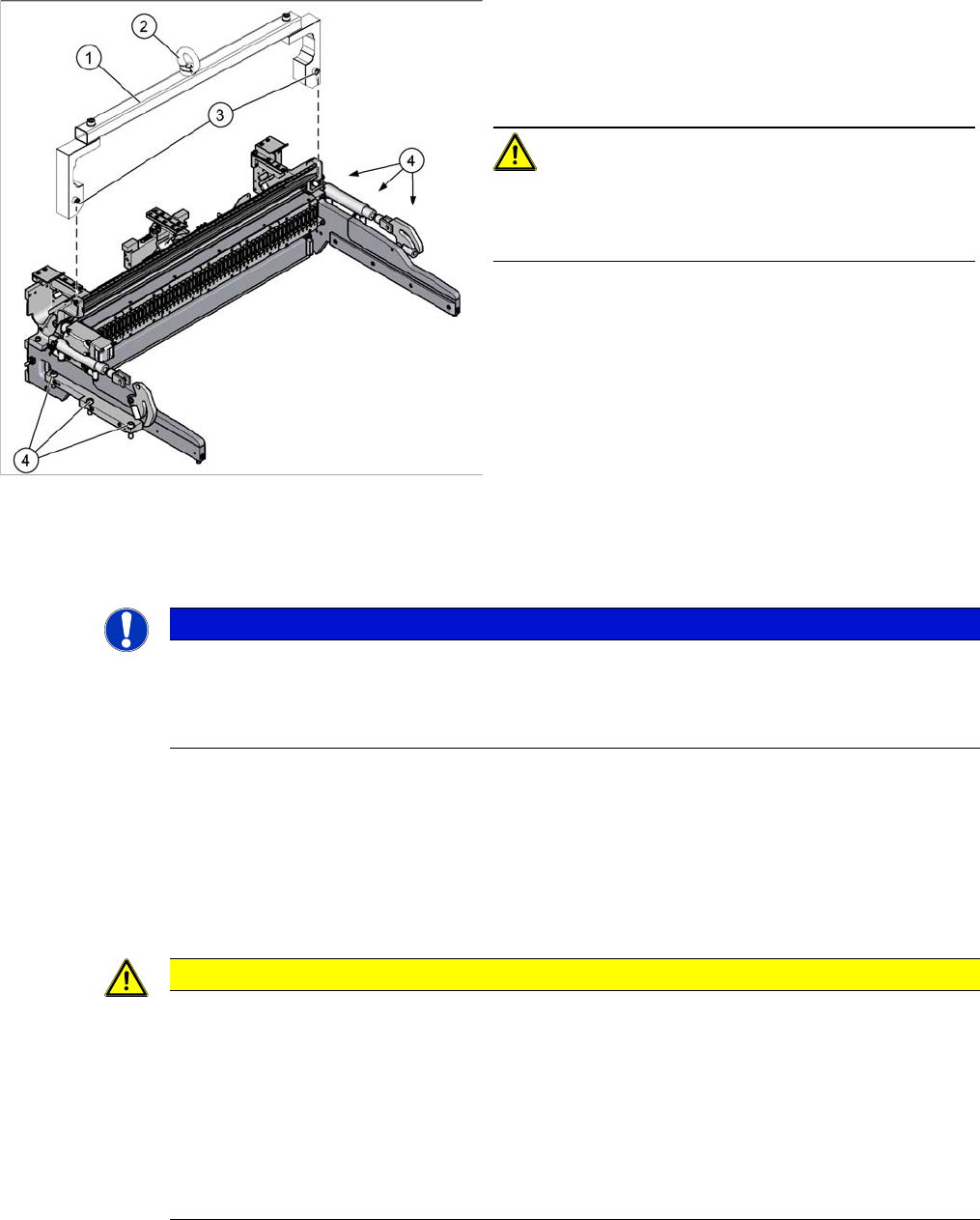
► Attach the fit-up aid to the fixtures provided on the COT insert.
► Remove the six screws fastening the COT insert.
► Fix the lifting device to the eyelet of the fit-up aid.
► Lift the complete COT insert out of the machine and place it on a suitable surface (e. g. four wooden
blocks).
Make sure not to damage any valves, connection cables, hoses, etc.
Installation
► Follow the removal instructions in reverse order for installation. Also observe the following instruc-
tions:
See also
4.5.1 Setting the Nozzle Changer Height (DLM, C&P20, CPP, TH) [ ➙ 271]
1. Fit-up aid
2. Eyelet
3. Fastening screws for fit-up aid
4. Fastening screws for COT insert
CAUTION!
Heavy machine part!
The COT insert is heavy. To lift it out, you will need to use
the fit-up aid and a suitable lifting device.
NOTICE
Marking the installation position
The COT insert can be installed at different positions (inner/outer) in the machine location. Mark
the position of your COT insert, to ensure that this is subsequently returned to its original posi-
tion.
CAUTION
Installation instructions
► Attach the fit-up aid to the new COT insert and lift it into the machine, with the help of the
lifting device.
► Make sure not to damage the cables and hoses.
► Observe the instructions in section "3.10.2.1 Fitting the Downholder" [ ➙ 209].
► Hook the waste tape chute into place. Please also observe section "3.10.10 Replacing the
Waste Tape Chute" [ ➙ 221]. Pay particular attention to the plastic strips and the fuses (if
present).
Service Work Conveyor
3.10.2 Replacing the SX1/SX2 Component Trolley Feed Device Assembly [03059353-xx] COT insert
Service Manual SIPLACE SX1/SX2/DX1/DX2 FS02 209
3.10.2.1
3.10.2.1 Fitting the Downholder
Fitting the Downholder
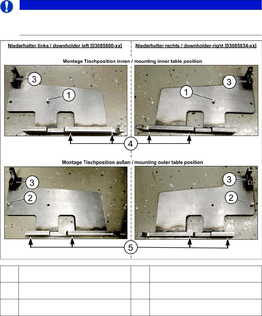
Preparing the downholder
Depending on the position of the component trolley (inside/outside), the downholder pin [03085247-xx]
is fitted either in position (1) or (2). This is then secured in place with a screw ISO4762-M6x12-A2-70
[03042572-xx].
After installation, the docking aid (3) docking aid on the downholder is always in the same position as
the docking unit that was previously dismantled (near the protective cover). The downholder pin and
therefore the assembly position of the downholder depends on the table position (inside/outside).
NOTICE
Only when table position changed
The downholder pin only needs to the converted if the table position inside/outside has been
changed.
1 Pin DIN6325-10-M6x30-St [00358814-xx]
at position inside
2 Pin DIN6325-10-M6x30-St [00358814-xx]
at position outside
3 Docking aid 4 Screw ISO4762-M8x40-A2-70 [03042589-
xx]
5 Screw ISO4762-M8x40-A2-70 [03042589-
xx]
Service Work Conveyor
COT insert 3.10.2 Replacing the SX1/SX2 Component Trolley Feed Device Assembly
210 Service Manual SIPLACE SX1/SX2/DX1/DX2 FS02
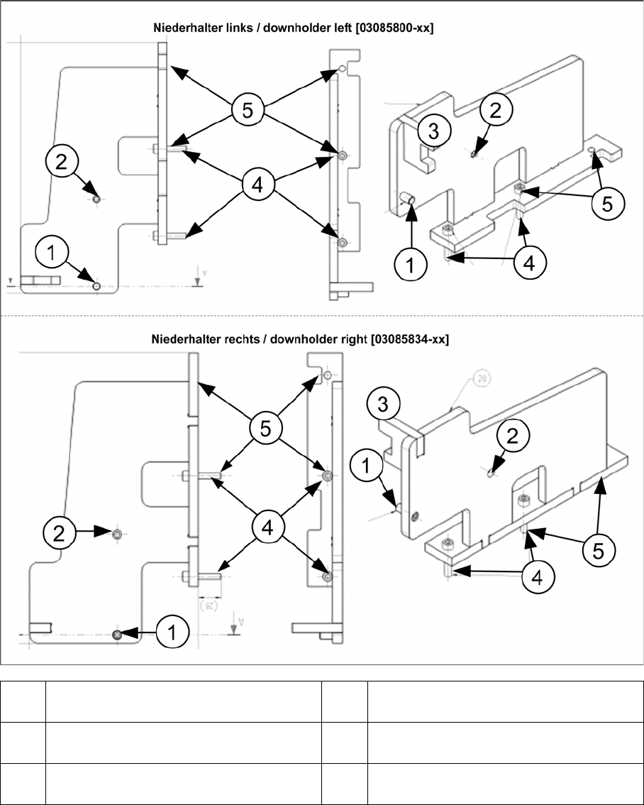
The position of the fastening screws (4) and (5) depends on the position of the COT insert.
When the table is in the inner position, the downholder pin (1) is moved approx. 125 mm inwards, to-
wards the docking aid (3) and the downholders are fixed with two new screws each to the position (4),
together with the COT insert.
When the table is in the outer position, the downholder pin (2) is underneath the docking aid (3) and the
downholders are fixed with two new screws each to the position (4), together with the COT insert.
1 Pin DIN6325-10-M6x30-St [00358814-xx]
at position inside
2 Pin DIN6325-10-M6x30-St [00358814-xx]
at position outside
3 Docking aid 4 Screw ISO4762-M8x40-A2-70 [03042589-
xx]
5 Screw ISO4762-M8x40-A2-70 [03042589-
xx]