00196497-07_SM_SXDX12_en.pdf - 第21页
Overview of the Modules 2.1.1 Serial Number of Module Overview of SX1/SX2/DX1/DX2 Service Manual SIPLACE SX1/SX2/DX1/DX2 FS02 21 2 2 O v e r v ie w o f t h e M o d u le s Overview of the Modules 2.1 2 . 1 O v e r v ie w …

Introduction
Abbreviations 1.3.7 SIPLACE on the World Wide Web (WWW)
20 Service Manual SIPLACE SX1/SX2/DX1/DX2 FS02
1.5
1.5 Abbreviations
Abbreviations
PA Placement area
CO Component
C&P Collect&Place
C&P12 Collect&Place head with 12 segments
C&P20 Collect&Place head with 20 segments
C&P6 Collect&Place head with 6 segments
CPP Collect&Pick&Place head
DC Dual conveyor
ESD Electrostatic sensitive device
EMC Electromagnetic compatibility
SC Single conveyor
FS, FS01, FS02 Function state, function state 01, function state 02
PCB Board
NC Nozzle changer
P&P Pick&Place
QC Quad lane conveyor
SC Station computer
TH TwinHead
VS Vision system type
ID, ID1, ID2 Intermediate distributor, intermediate distributor 1, intermediate distributor 2
Overview of the Modules
2.1.1 Serial Number of Module Overview of SX1/SX2/DX1/DX2
Service Manual SIPLACE SX1/SX2/DX1/DX2 FS02 21
2
2 Overview of the Modules
Overview of the Modules
2.1
2.1 Overview of SX1/SX2/DX1/DX2
Overview of SX1/SX2/DX1/DX2
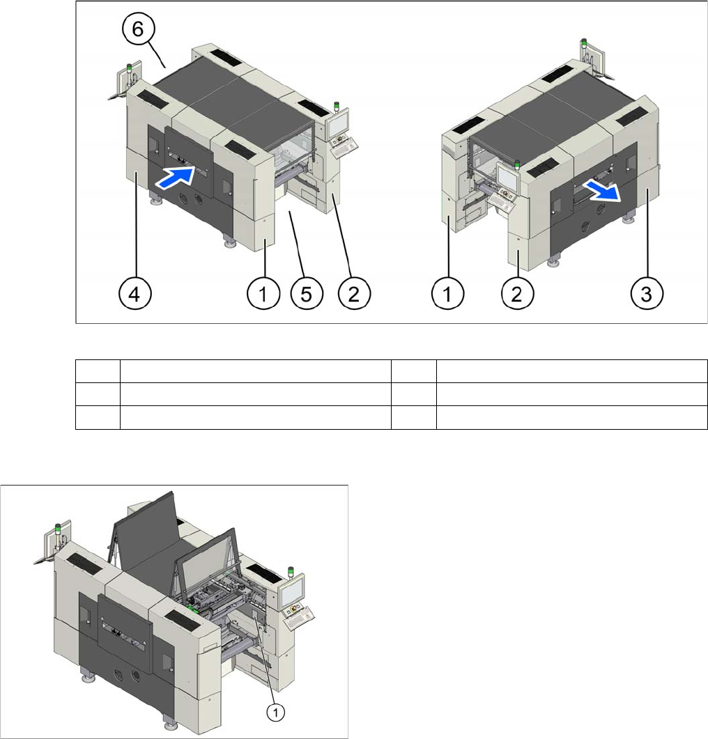
Overview (example of SX2 shown)
2.1.1
2.1.1 Serial Number of Module
Serial Number of Module
1 Sector 1 (pneumatic unit) 2 Sector 2
3 Sector 3 (power supply) 4 Sector 4
5 Location 1 6 Location 2
The serial number of your placement machine can be
found on the typeplate (1).
Overview of the Modules
Electrical System 2.2.1 BoxPC
22 Service Manual SIPLACE SX1/SX2/DX1/DX2 FS02
2.2
2.2 Electrical System
Electrical System
2.2.1
2.2.1 BoxPC
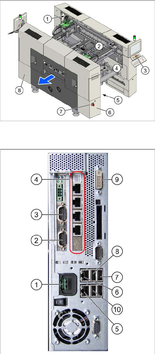
BoxPC
1. GCU (2x)
2. BoxPC
3. Start, stop and emergency stop button
4. GCU (for SX2)
5. Transformer module
This is in location 2, under the conveyor.
6. Power supply in sector 3
7. Main switch
8. Sector 2
The power pack unit [03072641-xx] with pulsed pow-
er pack PS3 26,8V, ballast resistor and fan are locat-
ed here.
1. Power supply DC 24 V
2. CAN 1 on the CAN bus card
3. CAN 2 on the CAN bus card
4. Hotlink card
5. LAN 2 – connection to Vision computer
(optional second BoxPC 3D Coplan)
6. LAN 1 – connection to SIPLACE Pro
(connection to line hub)
7. USB 0 – connection for keyboard/touchscreen (con-
nection to USB hub)
8. USB 2 – connection for an external DVD drive
9. DVI/VGA monitor connection
(connection to video multiplexer)
10. USB video multiplexer