00196497-07_SM_SXDX12_en.pdf - 第211页
Service Work Conveyor 3.10.2 Replacing the SX1/SX2 Component Trolley Feed Device Asse mbly [03059353-xx] COT insert Service Manual SIPLACE SX1/SX2/DX1/DX2 FS02 211 Fitting the right downholder ► Remove the two screws (4)…
Service Work Conveyor
COT insert 3.10.2 Replacing the SX1/SX2 Component Trolley Feed Device Assembly
210 Service Manual SIPLACE SX1/SX2/DX1/DX2 FS02
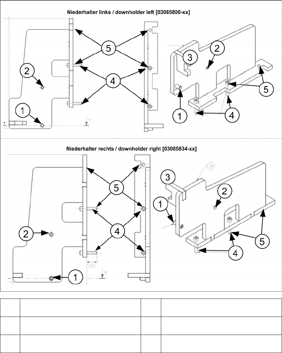
The position of the fastening screws (4) and (5) depends on the position of the COT insert.
When the table is in the inner position, the downholder pin (1) is moved approx. 125 mm inwards, to-
wards the docking aid (3) and the downholders are fixed with two new screws each to the position (4),
together with the COT insert.
When the table is in the outer position, the downholder pin (2) is underneath the docking aid (3) and the
downholders are fixed with two new screws each to the position (4), together with the COT insert.
1 Pin DIN6325-10-M6x30-St [00358814-xx]
at position inside
2 Pin DIN6325-10-M6x30-St [00358814-xx]
at position outside
3 Docking aid 4 Screw ISO4762-M8x40-A2-70 [03042589-
xx]
5 Screw ISO4762-M8x40-A2-70 [03042589-
xx]
Service Work Conveyor
3.10.2 Replacing the SX1/SX2 Component Trolley Feed Device Assembly [03059353-xx] COT insert
Service Manual SIPLACE SX1/SX2/DX1/DX2 FS02 211
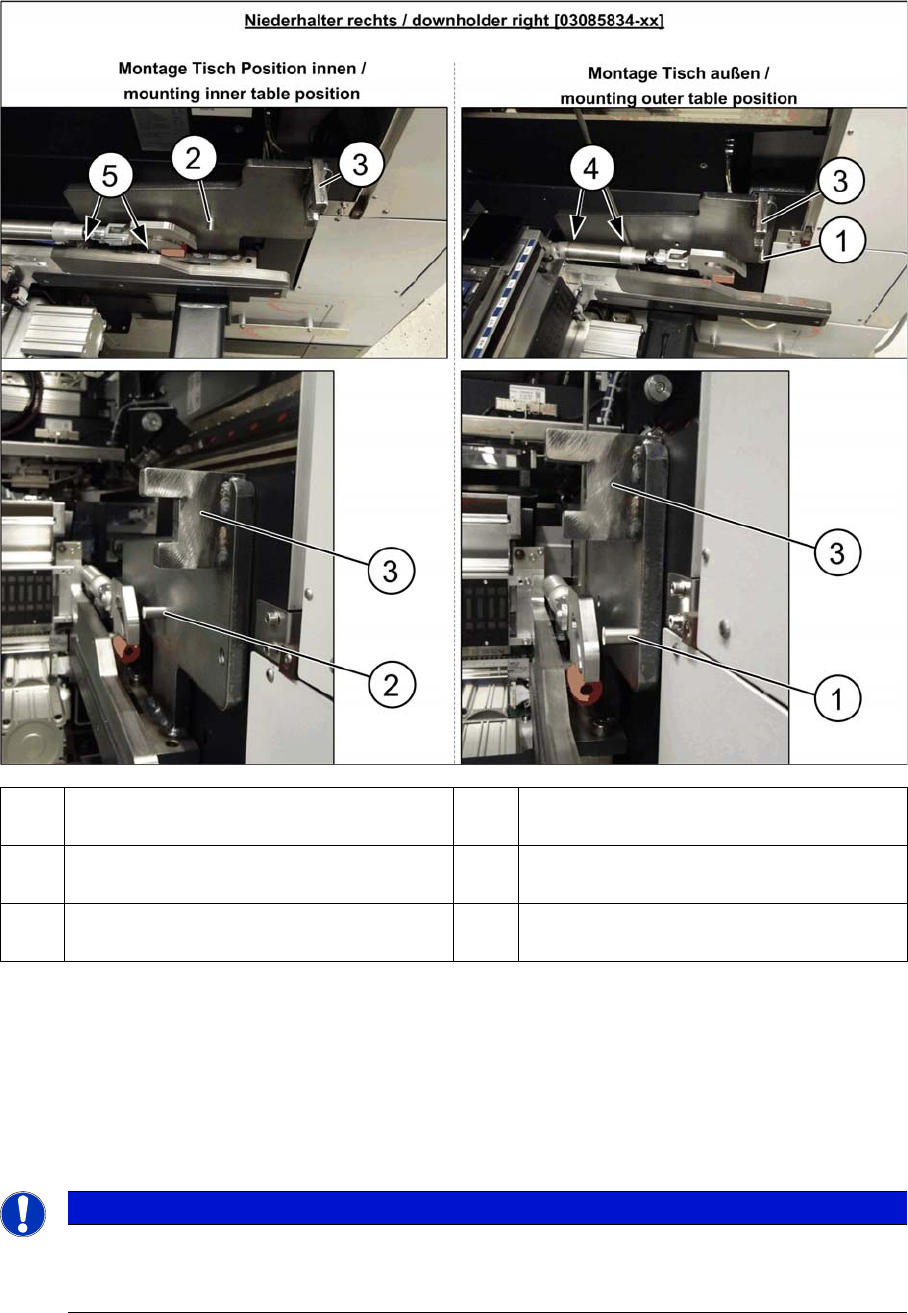
Fitting the right downholder
► Remove the two screws (4) and (5) on the right side of the COT insert. The screws are underneath
the COT insert cylinder.
► Place the "downholder COT-i right assembly" [03085834-xx] on the right side of the COT insert so
that the holes are aligned with one another.
► Screw the downholder tight with the two new screws (4) and (5).
► The downholder pin (2) must always be approx. 10 mm before the claws of the insert and the dock-
ing aid (3), behind the machine protection (cover flap).
1 Pin DIN6325-10-M6x30-St [00358814-xx]
at position inside
2 Pin DIN6325-10-M6x30-St [00358814-xx]
at position outside
3 Docking aid 4 Screw ISO4762-M8x40-A2-70 [03042589-
xx]
5 Screw ISO4762-M8x40-A2-70 [03042589-
xx]
NOTICE
Screws
Insert the new screws into the holes in the downholder and position the downholder together
with the screws onto the COT insert.
Service Work Conveyor
COT insert 3.10.2 Replacing the SX1/SX2 Component Trolley Feed Device Assembly
212 Service Manual SIPLACE SX1/SX2/DX1/DX2 FS02
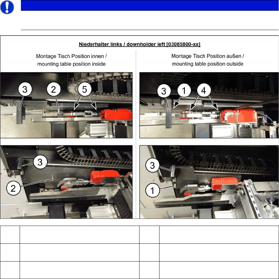
Fitting the left downholder
► Loosen the two screws (4) and (5) on the left side of the COT insert.
► Place the "downholder COT-i left assembly" [03085800-xx] on the left side of the COT insert so that
the holes are aligned with one another.
► Screw the downholder tight with the two new screws (4) and (5).
► The downholder pin (2) must always be approx. 10 mm before the claws of the insert and the dock-
ing aid (3), behind the machine protection (cover flap).
NOTICE
COT-I30 insert for the WPC
When using a COT-I30 insert for the WPC, you only need to fit the downholder on the right.
1 Pin DIN6325-10-M6x30-St [00358814-xx]
at position inside
2 Pin DIN6325-10-M6x30-St [00358814-xx]
at position outside
3 Docking aid 4 Screw ISO4762-M8x40-A2-70 [03042589-
xx]
5 Screw ISO4762-M8x40-A2-70 [03042589-
xx]