00196497-07_SM_SXDX12_en.pdf - 第215页
Service Work Conveyor 3.10.3 Replacing the Feeder Unlocking Device 60-fold [0305777 2- xx] COT insert Service Manual SIPLACE SX1/SX2/DX1/DX2 FS02 215 3.10.3 3 . 1 0 . 3 R e p la c in g t h e F e e d e r U n lo c k in g D…
Service Work Conveyor
COT insert 3.10.2 Replacing the SX1/SX2 Component Trolley Feed Device Assembly
214 Service Manual SIPLACE SX1/SX2/DX1/DX2 FS02
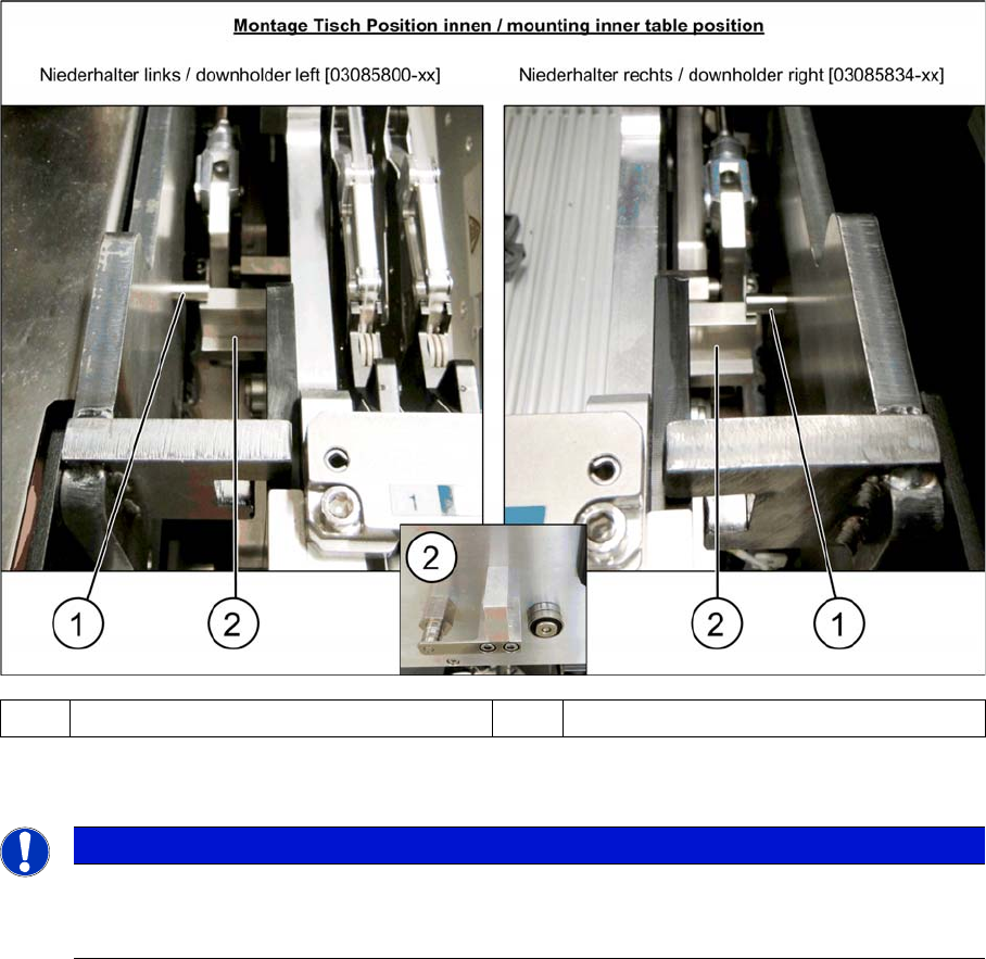
► After pulling the table in through the cylinder, the downholder pin (1) should be up, against the com-
ponent trolley downholder (2).
1 Downholder pin on the docking aid 2 Component trolley downholder
NOTICE
Wear
In the event of frequent component trolley cycle changes, these parts may become worn. Both
the downholder pin and the component trolley downholder are available as spare parts.
Service Work Conveyor
3.10.3 Replacing the Feeder Unlocking Device 60-fold [03057772-xx] COT insert
Service Manual SIPLACE SX1/SX2/DX1/DX2 FS02 215
3.10.3
3.10.3 Replacing the Feeder Unlocking Device 60-fold [03057772-xx]
Replacing the Feeder Unlocking Device 60-fold [03057772-xx]
Parts, Equipment and Tools
▪ SX1/SX2: feeder unlocking device 60-fold [03057772-xx] or
DX1/DX2: feeder unlocking device 60/2-fold [03082610-xx]
Overview
Removal
► Switch off the machine and secure it to prevent unauthorized reactivation. Observe the instructions
in section "1.2 Preparatory Work..." [ ➙ 13].
► Disconnect all electrical and pneumatic connections. You may want to mark their positions, to make
clear assignment easier later on.
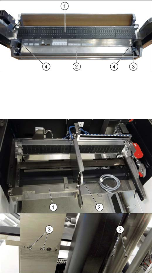
► Undo the two fastening screws and remove the feeder unlock device.
1. Feeder control unit (FCU)
2. Feeder unlock device (under the FCU)
3. Connector for flat ribbon cable
4. Fastening screws for feeder unlock device
If there is a WPC at the same location, perform the follow-
ing two steps as well:
► Dismantle the WPC docking rail (1).
► Dismantle the left side of the insert mechanism (2).
Remove the four fastening screws (3) on the under-
side and the two fastening screws on the top of the
tape duct.
Service Work Conveyor
COT insert 3.10.4 Replacing the Slotted Rail [03058008-xx]
216 Service Manual SIPLACE SX1/SX2/DX1/DX2 FS02
Installation
► Follow the removal instructions in reverse order for installation. Also observe the following instruc-
tions:
3.10.4
3.10.4 Replacing the Slotted Rail [03058008-xx]
Replacing the Slotted Rail [03058008-xx]
Parts, Equipment and Tools
▪ Slotted rail [03058008-xx]
Overview
Removal
► Switch off the machine and secure it to prevent unauthorized reactivation. Observe the instructions
in section "1.2 Preparatory Work..." [ ➙ 13].
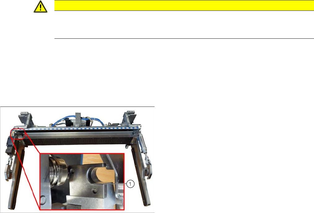
► Undo the two screws fastening the slotted rail and remove the slotted rail.
Installation
► Follow the removal instructions in reverse order for installation.
CAUTION
Installation instructions
► Make sure that you do not pinch or damage the cables run at the back (connected to the
FCU).
1. Slotted rail