00196497-07_SM_SXDX12_en.pdf - 第218页
Service Work Conveyor COT inse rt 3.10.6 Replacing the Insert Control [03123949- xx] 218 Service Manual SIPLACE SX1/SX2/DX1/DX2 FS02 3.10.6 3 . 1 0 . 6 R e p la c in g t h e I n s e r t C o n t r o l [ 0 3 1 2 3 9 4 9 - …
Service Work Conveyor
3.10.5 Replacing the Feeder Control Unit (FCU) [03059666-xx] COT insert
Service Manual SIPLACE SX1/SX2/DX1/DX2 FS02 217
3.10.5
3.10.5 Replacing the Feeder Control Unit (FCU) [03059666-xx]
Replacing the Feeder Control Unit (FCU) [03059666-xx]
Parts, Equipment and Tools
▪ SX1/SX2: B-FCU [03059666-xx] or
DX1/DX2: FCU [03082605-xx]
Overview
Removal
► Switch off the machine and secure it to prevent unauthorized reactivation. Observe the instructions
in section "1.2 Preparatory Work..." [ ➙ 13].
► Dismantle and remove the feeder unlock device. (See "3.10.3 Replacing the Feeder Unlocking De-
vice 60-fold [03057772-xx]" [ ➙ 215])
► Undo the two screws fastening the cover plate above the connectors of the FCU and remove the
cover plate.
► Unplug all cable connections for the FCU. You may want to mark their positions, to make clear as-
signment easier later on.
► Undo the four screws fastening the FCU and then remove the FCU.
Installation
► Follow the removal instructions in reverse order for installation. Also observe the following instruc-
tions:
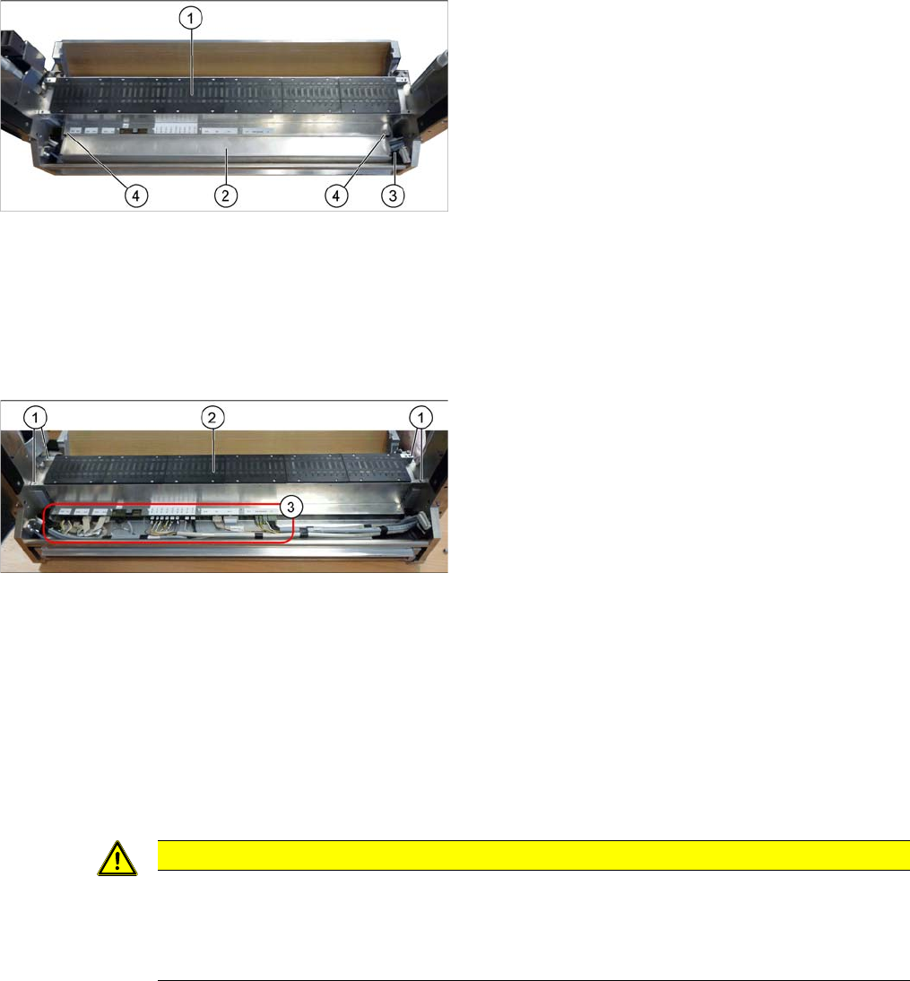
1. Feeder control unit (FCU)
2. Feeder unlock device (under the FCU)
3. Connector for flat ribbon cable
4. Fastening screws for feeder unlock device
1. Fastening screws for FCU
2. FCU
3. Electrical connections on the FCU
CAUTION
Installation instructions
► Set the DIP switches on the FCU (see "5.4.2 Connecting assy FCU [03059783-xx]"
[ ➙ 326]).
► Perform a BIOS download, if needed. (See "4.9.1 Firmware Download (SW 70x)" [ ➙ 293])
Service Work Conveyor
COT insert 3.10.6 Replacing the Insert Control [03123949-xx]
218 Service Manual SIPLACE SX1/SX2/DX1/DX2 FS02
3.10.6
3.10.6 Replacing the Insert Control [03123949-xx]
Replacing the Insert Control [03123949-xx]
Parts, Equipment and Tools
▪ Insert control SX1/2 cpl. [03123949-xx] (replaces [03079305-xx])
Overview
Removal
► Switch off the machine and secure it to prevent unauthorized reactivation. Observe the instructions
in section "1.2 Preparatory Work..." [ ➙ 13].
► To gain better access, you may need to disconnect the COT insert and pull it slightly out of the ma-
chine.
Alternatively, you can also remove the upper section of the component camera to gain better access.
► Unplug all electrical connections to the insert control. You may want to mark their positions, to make
clear assignment easier later on.
► Remove the screws fastening the insert control and remove the insert control from the machine.
Installation
► Follow the removal instructions in reverse order for installation.
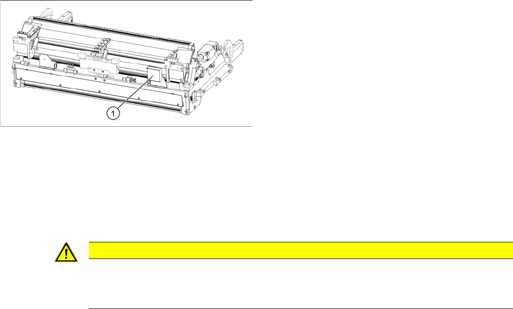
1. Insert control
CAUTION
Component Camera
► The component camera mirror has sharp edges.
► Take care not to damage the component camera.
Service Work Conveyor
3.10.7 Replacing the CAN Terminator Board [03046863-xx] (WPC5 feed-in only) COT insert
Service Manual SIPLACE SX1/SX2/DX1/DX2 FS02 219
3.10.7
3.10.7 Replacing the CAN Terminator Board [03046863-xx] (WPC5 feed-in only)
Replacing the CAN Terminator Board [03046863-xx] (WPC5 feed-in only)
Parts, Equipment and Tools
▪ CAN Bus terminator board for changeover table [03046863-xx]
Overview
Removal
► Switch off the machine and secure it to prevent unauthorized reactivation. Observe the instructions
in section "1.2 Preparatory Work..." [ ➙ 13].
► Unplug all electrical connections to the CAN terminator board. You may want to mark their positions,
to make clear assignment easier later on.
► Remove the screws fastening the CAN terminator board and remove the CAN terminator board from
the machine.
Installation
► Follow the removal instructions in reverse order for installation.
See also
5.4.3 CAN bus terminator for CO table [03046863-xx] [ ➙ 328]
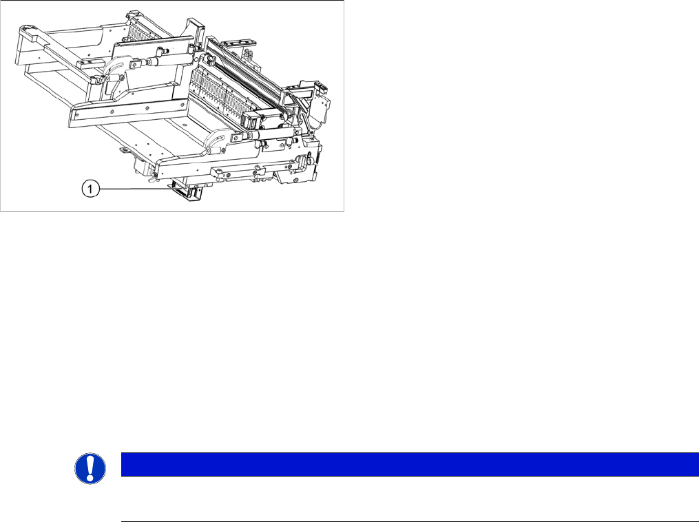
1. CAN terminator board
NOTICE
Installation instructions
► Set the DIP switches (see "5.4.3 CAN bus terminator for CO table [03046863-xx]" [➙328]).