00196497-07_SM_SXDX12_en.pdf - 第22页
Overview of the Modules Electrical System 2.2.1 BoxPC 22 Service Manual SIPLACE SX1/SX2/DX1/DX2 FS02 2.2 2 . 2 E le c t r ic a l S y s t e m Electrical System 2.2.1 2 . 2 . 1 B o x P C BoxPC 1. GCU (2x) 2. BoxPC 3. Start…
Overview of the Modules
2.1.1 Serial Number of Module Overview of SX1/SX2/DX1/DX2
Service Manual SIPLACE SX1/SX2/DX1/DX2 FS02 21
2
2 Overview of the Modules
Overview of the Modules
2.1
2.1 Overview of SX1/SX2/DX1/DX2
Overview of SX1/SX2/DX1/DX2
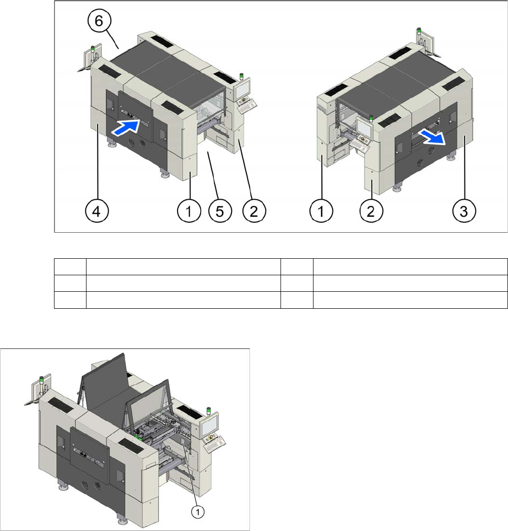
Overview (example of SX2 shown)
2.1.1
2.1.1 Serial Number of Module
Serial Number of Module
1 Sector 1 (pneumatic unit) 2 Sector 2
3 Sector 3 (power supply) 4 Sector 4
5 Location 1 6 Location 2
The serial number of your placement machine can be
found on the typeplate (1).
Overview of the Modules
Electrical System 2.2.1 BoxPC
22 Service Manual SIPLACE SX1/SX2/DX1/DX2 FS02
2.2
2.2 Electrical System
Electrical System
2.2.1
2.2.1 BoxPC
BoxPC
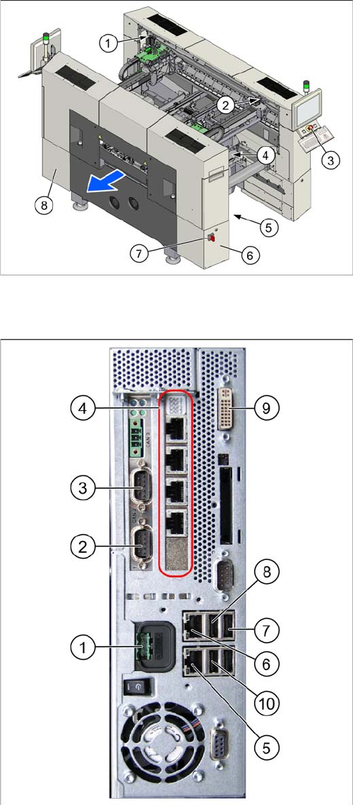
1. GCU (2x)
2. BoxPC
3. Start, stop and emergency stop button
4. GCU (for SX2)
5. Transformer module
This is in location 2, under the conveyor.
6. Power supply in sector 3
7. Main switch
8. Sector 2
The power pack unit [03072641-xx] with pulsed pow-
er pack PS3 26,8V, ballast resistor and fan are locat-
ed here.
1. Power supply DC 24 V
2. CAN 1 on the CAN bus card
3. CAN 2 on the CAN bus card
4. Hotlink card
5. LAN 2 – connection to Vision computer
(optional second BoxPC 3D Coplan)
6. LAN 1 – connection to SIPLACE Pro
(connection to line hub)
7. USB 0 – connection for keyboard/touchscreen (con-
nection to USB hub)
8. USB 2 – connection for an external DVD drive
9. DVI/VGA monitor connection
(connection to video multiplexer)
10. USB video multiplexer
Overview of the Modules
2.2.2 Power Supply [00354626-xx] Gantry
Service Manual SIPLACE SX1/SX2/DX1/DX2 FS02 23
2.2.2
2.2.2 Power Supply [00354626-xx]
Power Supply [00354626-xx]
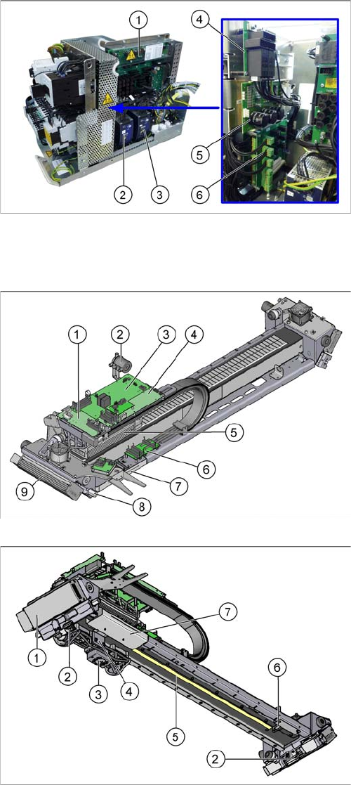
The power supply unit is mounted on a compact rack unit and is located in the left-hand middle section
of the machine. A lockable door prevents access to the power supply.
2.3
2.3 Gantry
Gantry
1. Fuse and connection board (A3)
2. Vision 24 VDC/42 VDC (PS2) (PULS power pack
42 VDC)
3. AC/DC converter (PS1) 25 V (PULS power pack
25 VDC)
4. Rectifier board (A7)
5. Load add circuit (A6)
6. Two boards are fitted above one another here.
Front: inrush current limitation board for transformer
(A1)
Behind: inrush current limitation board for servo (A2)
1. Vision board spread spectrum
2. Silencer
3. Base Adapter
4. Head interface
5. X axis motor (primary part)
6. Gantry interface X
7. Gantry interface Y (behind the cover)
8. Permanent lubrication Y axis floating bearing
9. Y axis motor (primary part)
1. Y axis motor (primary part)
2. Y axis incremental encoder (2x)
3. PCB Camera
4. X axis incremental encoder
5. X axis scale
6. Sensor interface (behind the cover)
7. Gantry interface Y (behind the cover)