00196497-07_SM_SXDX12_en.pdf - 第225页
Service Work Conveyor 3.11.1 Replacing the Cutter [03063781Sxx] Cutter Service Manual SIPLACE SX1/SX2/DX1/DX2 FS02 225 Installation ► Follow the removal in structions in reverse order for installati o n. Also observe the…
Service Work Conveyor
Cutter 3.11.1 Replacing the Cutter [03063781Sxx]
224 Service Manual SIPLACE SX1/SX2/DX1/DX2 FS02
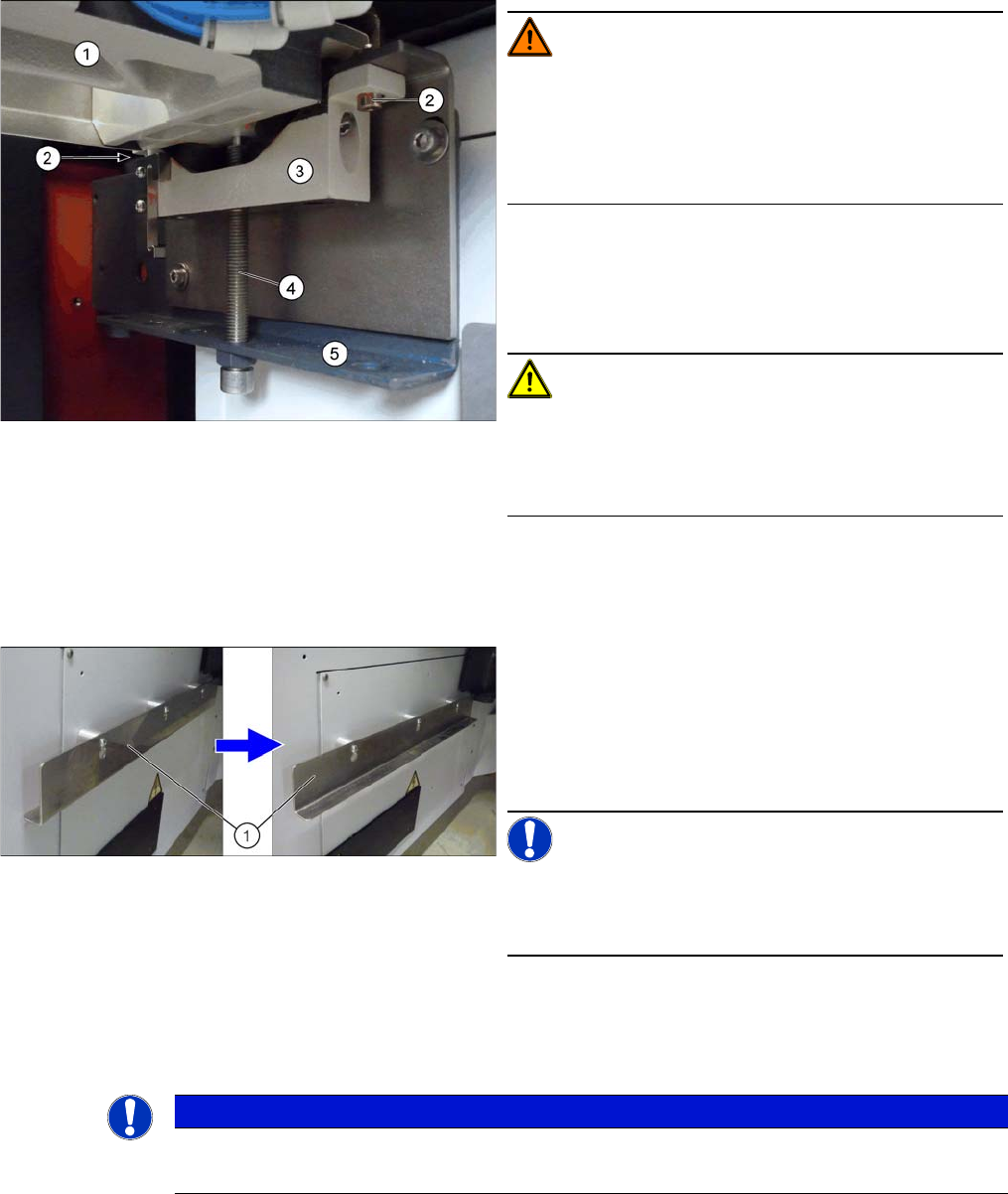
► Carefully lift the cutter out of the machine.
WARNING!
Risk of injury when releasing the fixtures!
The cutter (1) is only held by the fastening screws (2) and
is not supported by other parts.
If the 4 fastening screws are loosened without the cutter
being secured, this will fall down onto the bracket (5).
► Turn the two supporting screws (4) up to the top.
► Undo the 4 screws (2) fastening the brackets (3) of
the cutter and remove these brackets. The cutter is
now resting on the supporting screws.
CAUTION!
Only cutters with FS04:
There are small spacer disks on the top of the screw fix-
ture points for the mount (3). Make sure these are not
lost!
► Carefully lower the cutter onto the brackets by slowly
and evenly (right and left) lowering the supporting
screws.
► Turn the support plates (1) (angular plates) outwards
on the infrastructure cabinets.
To do this, loosen the screws fastening the support
plates.
Unhook the plates, rotate them and then retighten the
fastening screws.
NOTICE!
Support plates
You may need to fetch the support plates from another lo-
cation!
► The cutter can now be carefully pulled out towards
the front.
NOTICE
Heavy machine part!
► The cutter is heavy. You might need to enlist the help of a second person to prevent this.
Service Work Conveyor
3.11.1 Replacing the Cutter [03063781Sxx] Cutter
Service Manual SIPLACE SX1/SX2/DX1/DX2 FS02 225
Installation
► Follow the removal instructions in reverse order for installation. Also observe the following instruc-
tions:
► Hook the waste tape chute into place. Please also observe section "3.10.10 Replacing the Waste
Tape Chute" [ ➙ 221]. Pay particular attention to the plastic strips and the fuses (if present).
See also
1.2 Preparatory Work... [ ➙ 13]
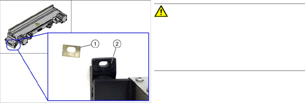
CAUTION!
Installation instructions
Cutters with FS04 have a spacer disk (1) at all 4 screw fix-
ture points (2).
Make sure that these disks are present when you fit the
cutter.
Otherwise there is a risk of head crash!
Service Work Conveyor
Cutter 3.11.2 Replacing the Proximity Switch [03061575]
226 Service Manual SIPLACE SX1/SX2/DX1/DX2 FS02
3.11.2
3.11.2 Replacing the Proximity Switch [03061575]
Replacing the Proximity Switch [03061575]
Parts, Equipment and Tools
▪ Proximity sensor with cable [03061575-xx]
▪ Sliding gauge [00094150-xx]
▪ Setting gauge for proximity switch buffer [03097370-xx]
Overview
Removal
► Switch off the machine, disconnect it from the power supply and secure it to prevent unauthorized
reactivation. Observe the instructions in section "1.2 Preparatory Work..." [ ➙ 13].
► Remove the fastening screws of the protective plate and lift it off. Also remove the cable tie on the
underside of the protective plate.
► Open the cable duct and pull the proximity switch cable out of the duct.
► Unplug the proximity switch connector. You may want to mark the connector positions, to make clear
assignment easier later on. (See "3.11.7 Connector Assignment on the Cutter" [ ➙ 244])
► Undo the screw fastening the proximity switch and then remove the switch.
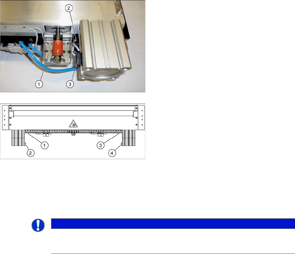
1. Protective plate
2. Proximity switch "out"
3. Proximity switch "in"
1. Proximity switch S1
2. Proximity switch S2
3. Proximity switch S3
4. Proximity switch S4
NOTICE
Dismantling the protective plate
Some versions of the cutter have holes drilled through the protective plate for the proximity
switch screws. In these versions, you do not need to dismantle the protective plate.