00196497-07_SM_SXDX12_en.pdf - 第239页
Service Work Conveyor 3.11.5 Replacing the Cutter Blades Cutter Service Manual SIPLACE SX1/SX2/DX1/DX2 FS02 239 ► Check the gap between the blades. If the gap is not correct , check: ▪ Has the wr ong downh older (vers io…
Service Work Conveyor
Cutter 3.11.5 Replacing the Cutter Blades
238 Service Manual SIPLACE SX1/SX2/DX1/DX2 FS02
Installation
► Insert the moveable blade with the return rods into the cutter.
► Connect the articulated joints of the short-stroke cylinder with the moveable blade. Tighten these
with a torque of 8.8 Nm. Secure the screws with Loctite. Fit the plastic covers on the screws and
knock into place with a rubber mallet.
► Make sure that all metal parts on the left and right of the cutter are clean. Otherwise there is a risk
of head crash!
► Fit the fixed blade onto the cutter. Tighten the screws to a torque of 8.8 Nm. Secure the screws with
Loctite.
► Fit the guidances, the upper cover plate and the shim plates with the four fastening screws on both
sides.
Make sure that all parts are flush against the outer side of the cutter.
Secure the screws with Loctite.
Tighten the screws to a torque of 8.8 Nm.
► Fit the plastic stoppers and elastomeric springs (see "3.11.6 Replacing the Elastomeric Spring
(Blade Damping)" [ ➙ 241]).
► Fit the return rods onto the moveable blade.
CAUTION!
Secure the screws with Loctite 243.
Make sure that the surfaces for the fork wrench on the re-
turn rods run parallel to the cutting edge of the moveable
blade.
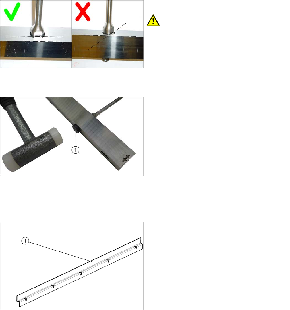
Do not unintentionally turn the blade. When viewed from
the side, the blade must get narrower the further down
you go.
► Insert the two plastic caps (1) onto the fastening
screws for the return rods and knock them into place
with a rubber mallet.
► Remove any excess edges on the plastic caps with a
knife.
► Insert the cover plate, tilted [0309872-xx] (1) with a
gap of 0.4mm +/-0.1mm to the blade.
Service Work Conveyor
3.11.5 Replacing the Cutter Blades Cutter
Service Manual SIPLACE SX1/SX2/DX1/DX2 FS02 239
► Check the gap between the blades.
If the gap is not correct, check:
▪ Has the wrong downholder (version < 03) been fitted?
The downholders are coordinated to the cutter with version 04 (= with deflector).
▪ Whether the blades, tape deflector etc. were cleaned before installation
If the gap is correct:
► Fit the connector with two fastening screws. Secure the screws with Loctite.
► Fit the protective plates onto the elastomeric springs. Secure the screws with Loctite.
► Fasten the cables into place on the protective plates with the help of cable ties.
► Reconnect the valves to the electricity supply.
► Reconnect the valves to the pneumatic supply.
► Refit the back cover. Secure the screws with Loctite.
► Follow the removal instructions in reverse order for further installation.
Installation – final work
Grease the cutter (see the maintenance manual for your machine) as follows:
► Fill the "grease gun with hose for Y axis" (volume applied approx. 0.4 g) [00374563-xx] with
Klüberplex BEM 34-132.
► Install the used tape chute. Please also observe section "3.10.10 Replacing the Waste Tape Chute"
[ ➙ 221]. Pay particular attention to the plastic strips and the fuses (if present).
CAUTION
Check how the cables and hoses are run!
Make sure that the cables and hoses are not pinched or subjected to excess strain.
► Position the hose of the grease gun straight onto the
lubrication nipple.
NOTICE!
If the lubrication nipple no longer lets lubricant through or
if it is damaged, replace it (DIN71412-A-M6 [03036936-
xx]).
► Press grease into the tape cutter until it visibly pro-
trudes out again.
► Remove excess grease with a brush.
► Repeat these steps for the other side of the tape cut-
ter.
► Repeat these steps for each tape cutter.
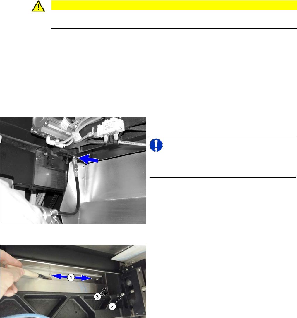
► Spray Interflon Fin grease into a suitable container.
► Distribute the grease with a brush to the underside of
the fixed blade (1).
► Remove any excess grease on the contact
surfaces (3) of the blades and the lubrication
nipples (2).

Service Work Conveyor
Cutter 3.11.5 Replacing the Cutter Blades
240 Service Manual SIPLACE SX1/SX2/DX1/DX2 FS02
Troubleshooting
See also
3.11.1 Replacing the Cutter [03063781Sxx] [ ➙ 223]
NOTICE
Error: cutter timing
If you are shown the machine error "cutter timing", this could be due to an imprecise arrange-
ment of the blades to one another. This arrangement can also be corrected when they are fitted.
► For more information about this, read section "3.11.6 Replacing the Elastomeric Spring
(Blade Damping)" [ ➙ 241].