00196497-07_SM_SXDX12_en.pdf - 第24页
Overview of the Modules Modular PCB Conveyor System 2.4.1 Single Conveyor 24 Service Manual SIPLACE SX1/SX2/DX1/DX2 FS02 2.4 2 . 4 M o d u la r P C B C o n v e y o r S y s t e m Modular PCB Conveyor System Your placement…
Overview of the Modules
2.2.2 Power Supply [00354626-xx] Gantry
Service Manual SIPLACE SX1/SX2/DX1/DX2 FS02 23
2.2.2
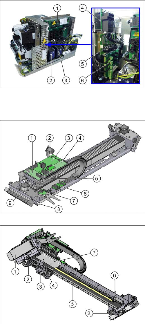
2.2.2 Power Supply [00354626-xx]
Power Supply [00354626-xx]
The power supply unit is mounted on a compact rack unit and is located in the left-hand middle section
of the machine. A lockable door prevents access to the power supply.
2.3
2.3 Gantry
Gantry
1. Fuse and connection board (A3)
2. Vision 24 VDC/42 VDC (PS2) (PULS power pack
42 VDC)
3. AC/DC converter (PS1) 25 V (PULS power pack
25 VDC)
4. Rectifier board (A7)
5. Load add circuit (A6)
6. Two boards are fitted above one another here.
Front: inrush current limitation board for transformer
(A1)
Behind: inrush current limitation board for servo (A2)
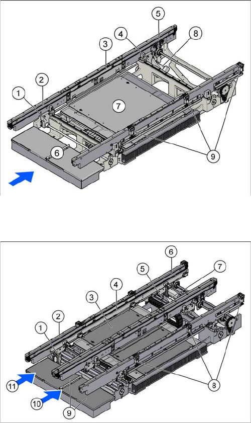
1. Vision board spread spectrum
2. Silencer
3. Base Adapter
4. Head interface
5. X axis motor (primary part)
6. Gantry interface X
7. Gantry interface Y (behind the cover)
8. Permanent lubrication Y axis floating bearing
9. Y axis motor (primary part)
1. Y axis motor (primary part)
2. Y axis incremental encoder (2x)
3. PCB Camera
4. X axis incremental encoder
5. X axis scale
6. Sensor interface (behind the cover)
7. Gantry interface Y (behind the cover)
Overview of the Modules
Modular PCB Conveyor System 2.4.1 Single Conveyor
24 Service Manual SIPLACE SX1/SX2/DX1/DX2 FS02
2.4
2.4 Modular PCB Conveyor System
Modular PCB Conveyor System
Your placement machine is either fitted with the single or dual conveyor, depending on the configuration.
2.4.1
2.4.1 Single Conveyor
Single Conveyor
2.4.2
2.4.2 Dual Conveyor
Dual Conveyor
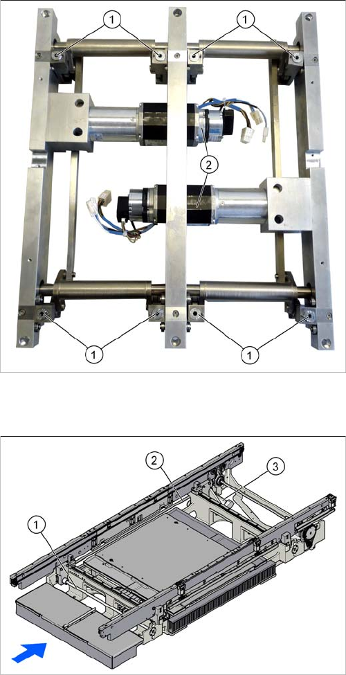
1. Width adjustment in the input area
2. Input area
3. Placement area
4. Width adjustment in the output area
5. Output area
6. Conveyor control TSP400 (under the cover)
7. Lifting table
8. Conveyor drive
9. Stopper (3 x)
The dual conveyor has got two conveyor lanes. In the
standard version, the fixed conveyor side wall of each
conveyor lane is on the right-hand side.
1. Width adjustment in the input area
2. Input area
3. Lifting table
4. Placement area
5. Width adjustment in the output area
6. Output area
7. Conveyor drive
8. Stoppers (3 x per conveyor lane)
9. 2x conveyor control TSP400 (under the covers)
10. Conveyor lane 1
11. Conveyor lane 2
Overview of the Modules
2.4.3 Lifting Table Modular PCB Conveyor System
Service Manual SIPLACE SX1/SX2/DX1/DX2 FS02 25
2.4.3
2.4.3 Lifting Table
Lifting Table
2.4.4
2.4.4 Width Adjustment
Width Adjustment
The lifting table with the example of the dual conveyor.
The lifting table for the single conveyor has the same de-
sign.
1. Lifting table plate guides incl. setting options for align-
ment
2. Lifting table motors with integrated measurement
system and brake
Width adjustment for single conveyor
1. Recirculating spindle
2. Toothed belt of width adjustment
3. Drive unit of width adjustment