00196497-07_SM_SXDX12_en.pdf - 第241页
Service Work Conveyor 3.11.6 Replacing the Elastomeric Spring (Blade Damping) Cutter Service Manual SIPLACE SX1/SX2/DX1/DX2 FS02 241 3.11.6 3 . 1 1 . 6 R e p la c in g t h e E la s t o m e r ic S p r in g ( B la d e D a …

Service Work Conveyor
Cutter 3.11.5 Replacing the Cutter Blades
240 Service Manual SIPLACE SX1/SX2/DX1/DX2 FS02
Troubleshooting
See also
3.11.1 Replacing the Cutter [03063781Sxx] [ ➙ 223]
NOTICE
Error: cutter timing
If you are shown the machine error "cutter timing", this could be due to an imprecise arrange-
ment of the blades to one another. This arrangement can also be corrected when they are fitted.
► For more information about this, read section "3.11.6 Replacing the Elastomeric Spring
(Blade Damping)" [ ➙ 241].
Service Work Conveyor
3.11.6 Replacing the Elastomeric Spring (Blade Damping) Cutter
Service Manual SIPLACE SX1/SX2/DX1/DX2 FS02 241
3.11.6
3.11.6 Replacing the Elastomeric Spring (Blade Damping)
Replacing the Elastomeric Spring (Blade Damping)
Parts, equipment and tools
▪ Elastomeric spring 20x8.5x22 (90 Shore A) [03096352-xx]
▪ Plastic stopper for cutter SX1/SX2 [03096297-xx]
▪ Setting gauge for proximity switch buffer [03097370-xx]
▪ Loctite 243 locking varnish 10 ml [00334892-xx]
Overview
NOTICE
Replace in pairs
We recommend that you always replace the elastomeric springs in pairs. However, they can be
replaced individually if necessary.
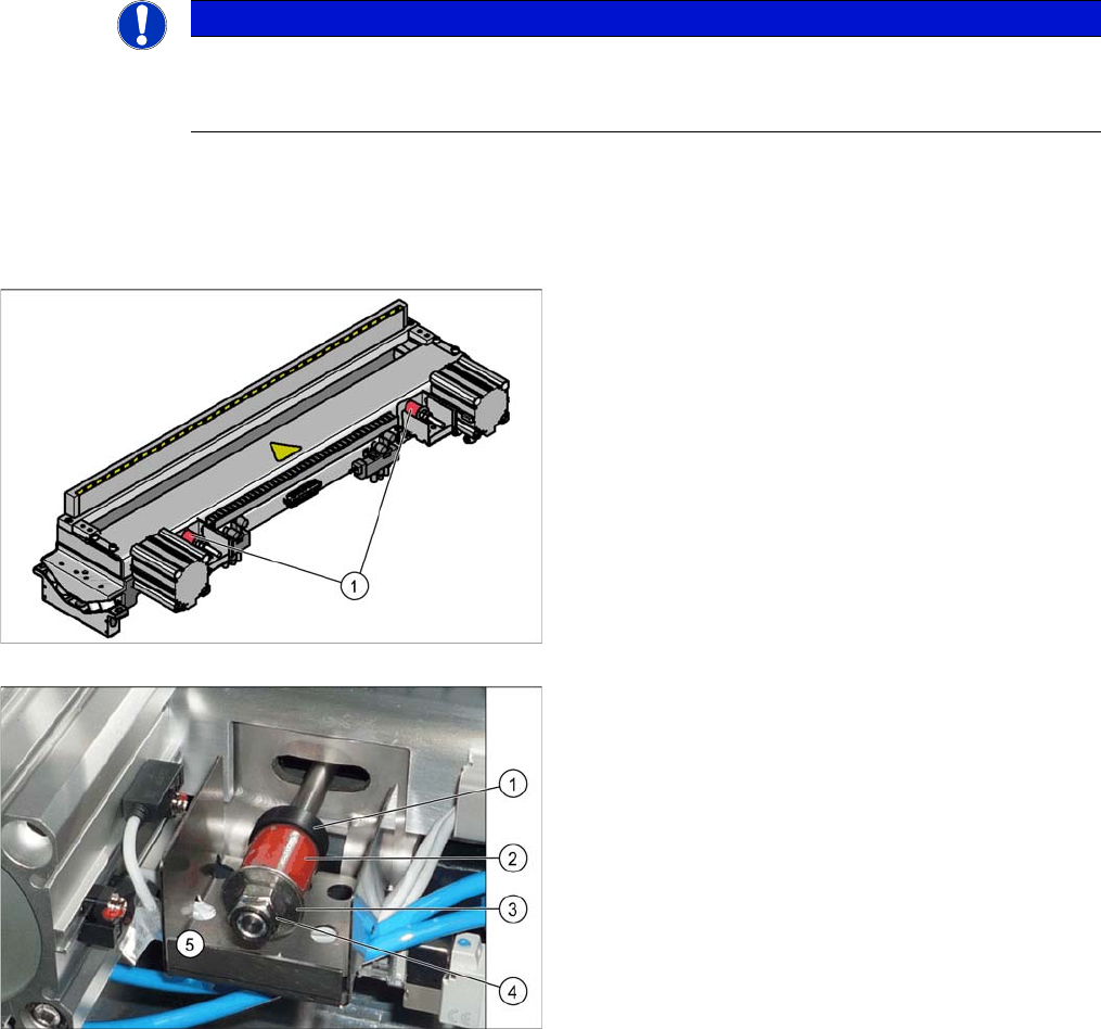
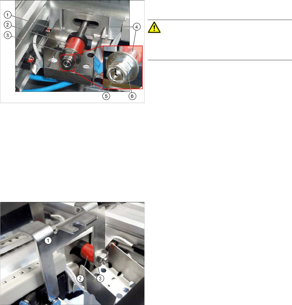
1. Elastomeric spring on cutter
1. Plastic stopper
2. Elastomeric spring
3. Washer
4. 2 x fastening screws
5. Protective plate
Service Work Conveyor
Cutter 3.11.6 Replacing the Elastomeric Spring (Blade Damping)
242 Service Manual SIPLACE SX1/SX2/DX1/DX2 FS02
Removal
► Switch off the machine, disconnect it from the power supply and secure it to prevent unauthorized
reactivation. Observe the instructions in section "1.2 Preparatory Work..." [ ➙ 13].
► Unhook the waste tape chute.
Installation
► Clean the return rod to remove any residue varnish. Make sure you do not wipe away the markings.
► Check whether the marking is still vertical.
If it is not, adjust it accordingly. (See "3.11.5 Replacing the Cutter Blades" [ ➙ 234])
► Press against the two return rods until the movable and the fixed blade overlap.
► Fit the plastic stopper [03096297-xx], the elastomeric spring [03096352-xx] and the washer in this
order onto the return rod.
► Apply Loctite 243 to the return rod.
► Screw the wide nut onto the return rod.
► Use a pen to mark the return rod (4) with a vertical
mark (5).
CAUTION!
The retaining rods may not be distorted. Use the marking
on them to guide you.
Make sure you do not wipe away the markings.
► Loosen the screws (6) fastening the return rod. Make
sure that you do not rotate the return rod out of posi-
tion.
► Remove the washer (3), the elastomeric spring (2)
and the plastic stopper (1)from the return rod.
► Insert the setting gauge (1) as shown in the diagram,
between the washer (3) and the elastomeric
spring (2). The setting gauge is used to set a defined
overlap of the blades during cutting.