00196497-07_SM_SXDX12_en.pdf - 第25页
Overview of the Modules 2.4.3 Lifting Table Modular PCB Conveyor System Service Manual SIPLACE SX1/SX2/DX1/DX2 FS02 25 2.4.3 2 . 4 . 3 L if t in g T a b le Lifting Table 2.4.4 2 . 4 . 4 W id t h A d ju s t m e n t Width …
Overview of the Modules
Modular PCB Conveyor System 2.4.1 Single Conveyor
24 Service Manual SIPLACE SX1/SX2/DX1/DX2 FS02
2.4
2.4 Modular PCB Conveyor System
Modular PCB Conveyor System
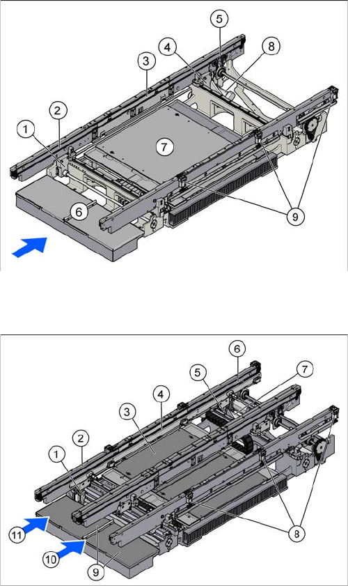
Your placement machine is either fitted with the single or dual conveyor, depending on the configuration.
2.4.1
2.4.1 Single Conveyor
Single Conveyor
2.4.2
2.4.2 Dual Conveyor
Dual Conveyor
1. Width adjustment in the input area
2. Input area
3. Placement area
4. Width adjustment in the output area
5. Output area
6. Conveyor control TSP400 (under the cover)
7. Lifting table
8. Conveyor drive
9. Stopper (3 x)
The dual conveyor has got two conveyor lanes. In the
standard version, the fixed conveyor side wall of each
conveyor lane is on the right-hand side.
1. Width adjustment in the input area
2. Input area
3. Lifting table
4. Placement area
5. Width adjustment in the output area
6. Output area
7. Conveyor drive
8. Stoppers (3 x per conveyor lane)
9. 2x conveyor control TSP400 (under the covers)
10. Conveyor lane 1
11. Conveyor lane 2
Overview of the Modules
2.4.3 Lifting Table Modular PCB Conveyor System
Service Manual SIPLACE SX1/SX2/DX1/DX2 FS02 25
2.4.3
2.4.3 Lifting Table
Lifting Table
2.4.4
2.4.4 Width Adjustment
Width Adjustment
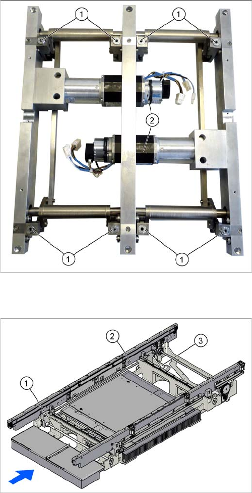
The lifting table with the example of the dual conveyor.
The lifting table for the single conveyor has the same de-
sign.
1. Lifting table plate guides incl. setting options for align-
ment
2. Lifting table motors with integrated measurement
system and brake
Width adjustment for single conveyor
1. Recirculating spindle
2. Toothed belt of width adjustment
3. Drive unit of width adjustment
Overview of the Modules
Modular PCB Conveyor System 2.4.4 Width Adjustment
26 Service Manual SIPLACE SX1/SX2/DX1/DX2 FS02
Function Description
The width is adjusted by means of a motor as programmed. For dual conveyor systems, differing widths
can be set for the two conveyor lanes. The width adjustment uses a motor with its own measuring sys-
tem, meaning that the PCB width can be set independently of other machine components (e.g. the Y
gantry).
The PCB width is adjusted using two width adjustment units, which are fitted in the input and output ar-
eas. These adjustment units are moved synchronously back and forth by the drive motor, with the help
of recirculating spindles and a toothed belt.
In the dual conveyor, the fixing pins are moved out to release the side clamp. At the same time, the side
is fixed to the adjustment unit. After reaching the new PCB width, both fixing pins move back in. The
conveyor side is then clamped again.
In the single conveyor, the flexible side is moved directly by the two recirculating spindles of the adjust-
ment units.
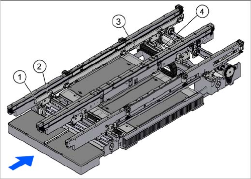
Width adjustment for dual conveyor
1. Adjustment unit
2. Recirculating spindle
3. Toothed belt of width adjustment
4. Drive unit of width adjustment