00196497-07_SM_SXDX12_en.pdf - 第254页
Settings Settings on the Basic Machine 4.2.1 Setting the Machine Covers 254 Service Manual SIPLACE SX1/SX2/DX1/DX2 FS02 4.2.1.8 4 . 2 . 1 . 8 S e t t in g t h e C o v e r R o lle r s Setting the Cover Rollers Cover rolle…
Settings
4.2.1 Setting the Machine Covers Settings on the Basic Machine
Service Manual SIPLACE SX1/SX2/DX1/DX2 FS02 253
4.2.1.7
4.2.1.7 Setting the Bottom Stop
Setting the Bottom Stop
► Check the settings by opening and carefully closing the cover several times:
▪ The metal bracket is parallel to the opening and does not scrape against the switch
▪ The plastic centering feature is positioned centrally to the centering device and does not scrape
against the switch.
▪ When the cover is opened, there is no discernable resistance of the cover rollers in the guidance
rails.
▪ Shortly before the bottom cover position, there is no resistance audible apart from the centering en-
gaging and the engaging of the metal bracket in the cover switch.
▪ The cover can be closed completely, so that the swing cover closes smoothly at the top with the side
covers.
NOTICE
Observing the Technical Information
► Also observe the Technical Information "New stopper on folding covers for SIPLACE SX1
/ DX1" [DE: TI2014-04D05] [EN: TI2014-04E05].
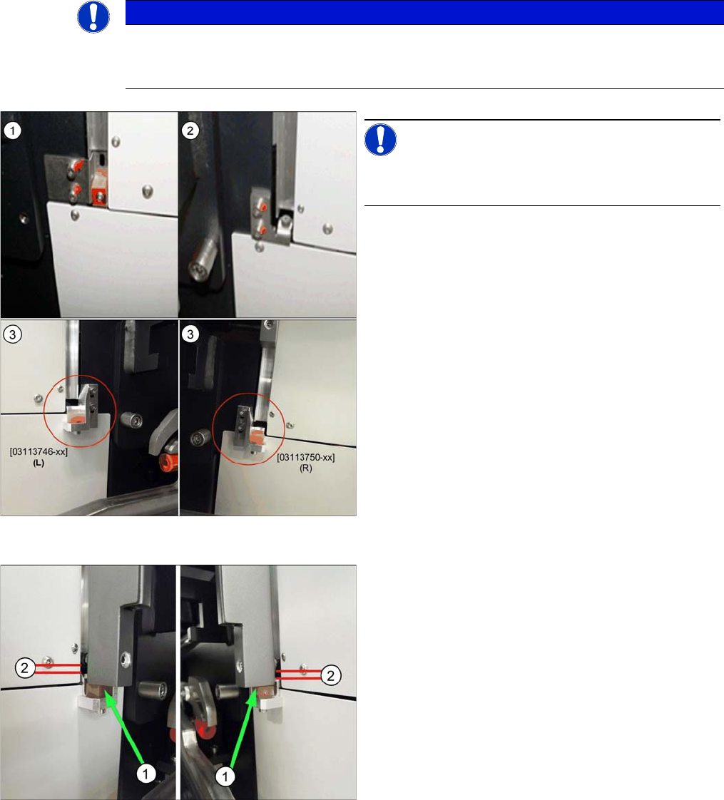
Bottom stop (example of SX2 shown )
NOTICE!
There are three variants of the bottom stop.
We recommend a conversion to variant 3.
1. Variant 1 (SX1/SX2) (old):
2x buffer cover guidance [03075364-xx]
1x DIN EN ISO7380-M3 x 25-A2-70 [03045198-xx]
1x DIN985 - M3 - A2-70 [00328897-xx]
2. Variant 2 (SX1/SX2, X-Series S) (old):
Right stop [03086295-02]
Left stop [03086313-02]
Buffer with studs, type no. 1284 [03072728-01]
3. Variant 3 (new)
Right stop cpl. [03113750-xx]
Left stop cpl. [03113746-xx]
Setting the stop for variant 3:
► Set the stop in such a way that the cover lies on the
buffer (1). When closing the cover, make sure that
the cover lies on the buffer first.
► The cover roller (2) must still be in the guide and must
not lie on the stop.
Settings
Settings on the Basic Machine 4.2.1 Setting the Machine Covers
254 Service Manual SIPLACE SX1/SX2/DX1/DX2 FS02
4.2.1.8
4.2.1.8 Setting the Cover Rollers
Setting the Cover Rollers
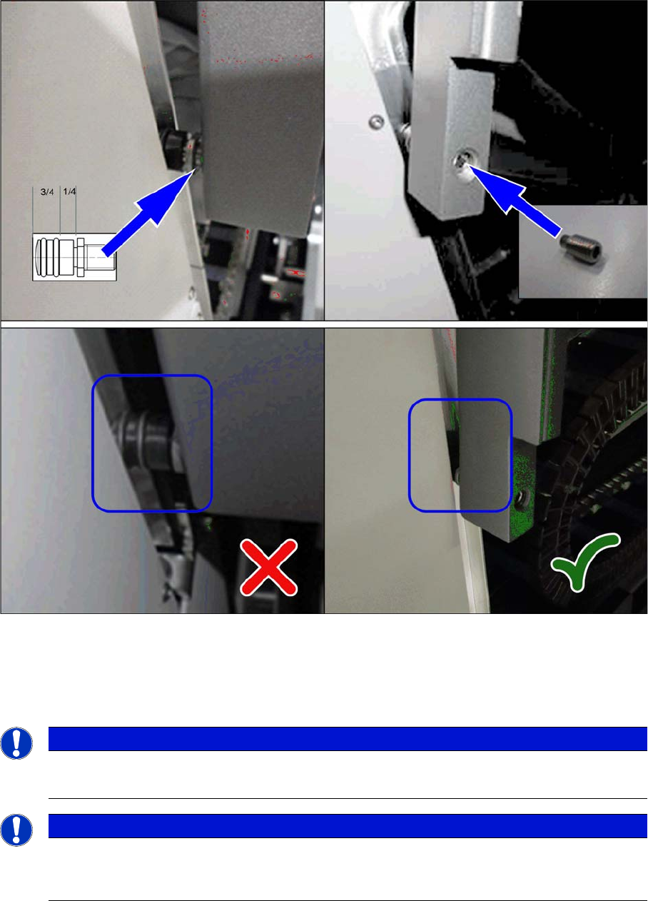
Cover rollers (example of SX2 shown)
► Set the cover roller by using the grub screw, so that it is inserted by at least 75% into the guidance,
along its whole length. Lock the roller with a setscrew DIN915-M8x16 [00304354-xx] or DIN-EN-
ISO4026-M8x16-A2-21H [03025582-xx].
Place shims between the roller and cover for greater stability.
NOTICE
Missing O-rings
► Replace the following missing O-rings on the roller: O-ring 8.5x1.6 [03078577-xx]
NOTICE
Maintenance
There are O-rings on the roller. These need to be checked every 6 months and replaced when
necessary. If the roller or bottom stop is already damaged, this will also need to be replaced.
Settings
4.3.1 Fuses Electrical and Control Settings
Service Manual SIPLACE SX1/SX2/DX1/DX2 FS02 255
4.3
4.3 Electrical and Control Settings
Electrical and Control Settings
4.3.1
4.3.1 Fuses
Fuses
For more information about this, read section "5.1.4 Fuse Connection Board" [ ➙ 309].
4.3.2
4.3.2 Setting the Voltage on the AC/DC Converters
Setting the Voltage on the AC/DC Converters
Parts, Equipment and Tools
▪ Voltage measuring device
Overview
The AC/DC converters are located at the following positions:
▪ PS1: in sector 3 on the power supply switching unit (25 V)
AC/DC converter DC24V/20A 3 phase [03055232-xx]
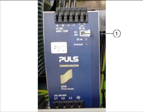
▪ PS2: in sector 3 on the power supply switching unit (42 V)
AC/DC converter DC36-42V/13.3A 3 phase [03076588-xx]
▪ PS3: in sector 2 (26,8 V)
AC/DC converter DC24V/20A 3 phase [03055232-xx]
Setting
Setting the AC/DC converter
► Open the protective cap on the setting screw (1).
► Rotate with a slotted screwdriver until the AC/DC
converter provides the correct voltage.
Use a suitable voltage measuring device to check the
voltage between the + and – terminals.