00196497-07_SM_SXDX12_en.pdf - 第262页
Settings Electrical and Control Settings 4.3.5 Setting the DIP Switch on the CAN Sw itch 262 Service Manual SIPLACE SX1/SX2/DX1/DX2 FS02 DIP switch S1 in CAN switch [03083844-xx] The DI P switch setting S1.3 to S1. 5 is …
Settings
4.3.5 Setting the DIP Switch on the CAN Switch Electrical and Control Settings
Service Manual SIPLACE SX1/SX2/DX1/DX2 FS02 261
► Reboot your machine and check the operating system to make sure that the CAN driver has been
correctly installed or that the firmware and serial number are recognized correctly.
4.3.5
4.3.5 Setting the DIP Switch on the CAN Switch
Setting the DIP Switch on the CAN Switch
► Disconnect the CAN switch from the voltage supply.
► Loosen the two screws fastening the upper section (side with label) and remove it.
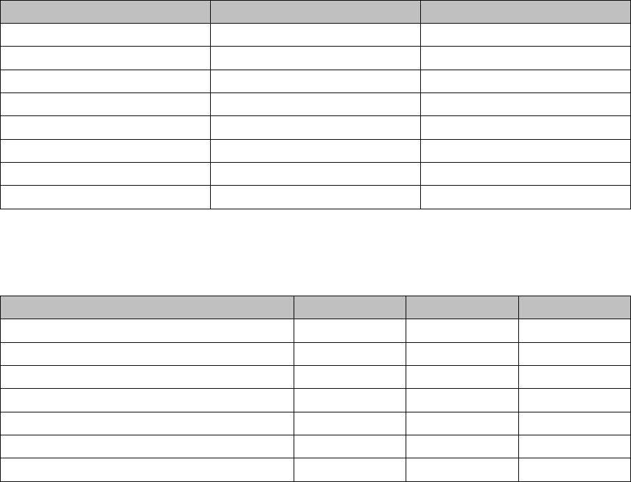
► Set the DIP switches:
Board in CAN switch [03083844-xx]
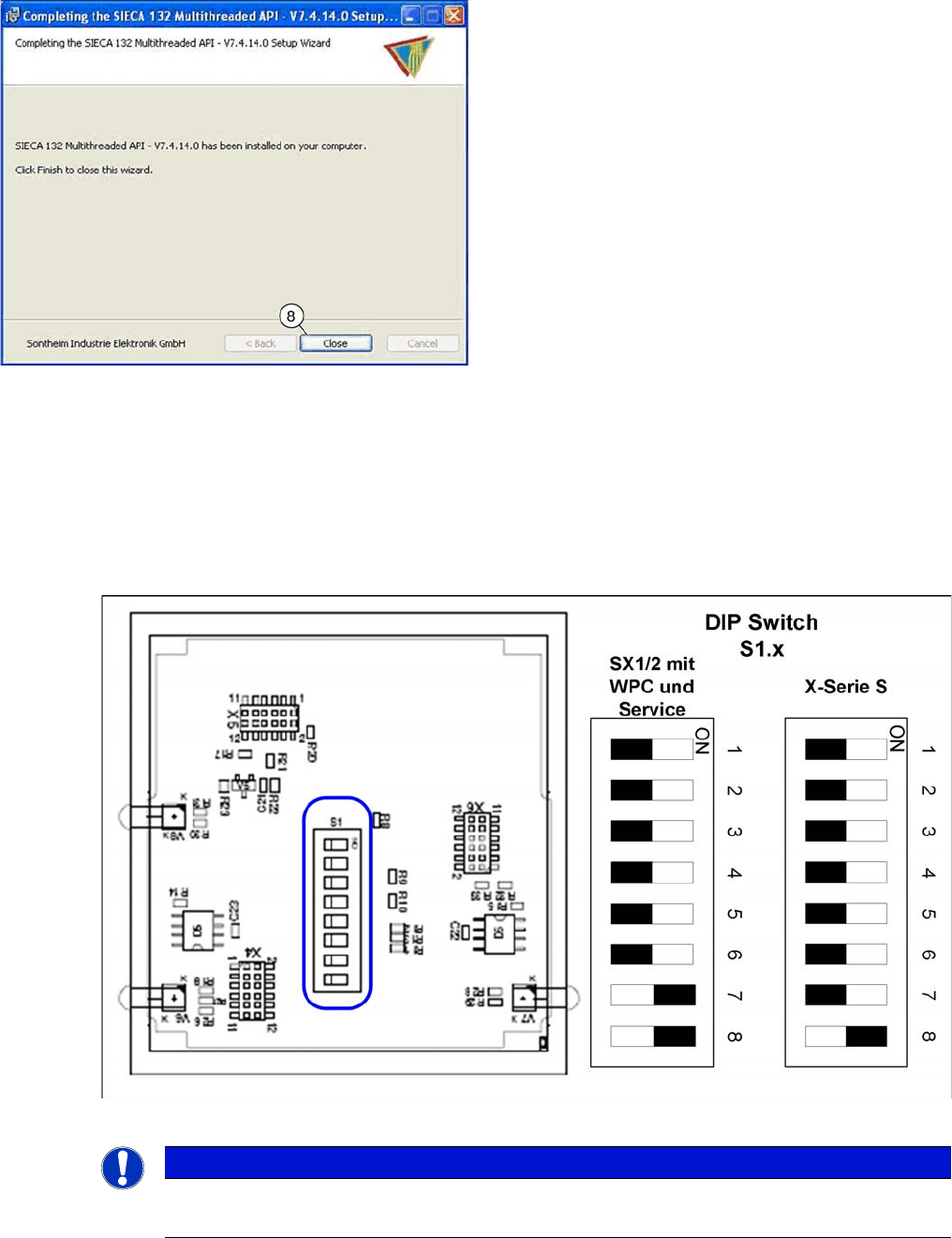
► Once the installation has finished, click on the "Close"
(8) button to close the installation wizard.
NOTICE
Default setting
The CAN switch is preset as a default for the X-Series S.
Settings
Electrical and Control Settings 4.3.5 Setting the DIP Switch on the CAN Switch
262 Service Manual SIPLACE SX1/SX2/DX1/DX2 FS02
DIP switch S1 in CAN switch [03083844-xx]
The DIP switch setting S1.3 to S1.5 is used to configure the display (LED) i.e the number of error frames
needed for the LED to change its status from green to red. The default setting is that the LED turns red
for each error frame received.
LED status error frames
DIP switch S1 ON OFF
S1.1 Test mode Normal mode
S1.2 500 kBaud 1 MBaud
S1.3 See table below See table below
S1.4 See table below See table below
S1.5 See table below See table below
S1.6 ASC Test ON ASC Test OFF
S1.7 120 Ohm CAN 1 No terminal resistor
S1.8 120 Ohm CAN 2 No terminal resistor
LED status S1.3 S1.4 S1.5
1 error frame OFF OFF OFF
5 Error frames/minute ON OFF OFF
10 Error frames/minute OFF ON OFF
10 Error frames/hour ON ON OFF
50 Error frames/hour OFF OFF ON
100 Error frames/hour ON OFF ON
500 Error frames/hour OFF ON ON
Settings
4.4.1 Travel Ranges and Speed Monitoring Gantry Settings
Service Manual SIPLACE SX1/SX2/DX1/DX2 FS02 263
4.4
4.4 Gantry Settings
Gantry Settings
See also
5.2.1 Head Interface C700B [03055072-xx] [ ➙ 311]
4.4.1
4.4.1 Travel Ranges and Speed Monitoring
Travel Ranges and Speed Monitoring
The travel range of the X and Y axes will be determined automatically with the help of the software.
4.4.2
4.4.2 Anticrash Function
Anticrash Function
The anticrash function is realized via the GCU software.
4.4.2.1
4.4.2.1 Anticrash Function - Tasks
Anticrash Function - Tasks
▪ Monitoring the X and Y axis travel ranges
Evaluation of the actual position of the respective axis in the direction of the bumper, based on the
speed.
▪ Monitoring the distance of both Y axes in a placement area
Evaluation of the actual position of the own gantry and the partner gantry at gantry crash monitoring.
▪ Count error monitoring of the gantry axis
Monitoring incoming count pulses (edge control) over time.
4.4.2.2
4.4.2.2 Anticrash Function - Procedure
Anticrash Function - Procedure
The anticrash function is activated after the X/Y axes have been referenced. When the gantry axes are
referenced for the first time, anticrash monitoring is not active, which does not matter, due to the low ref-
erence speed.
The bit for the anticrash monitor is then set via the FDB (Fast-Drive-Bus). There is continuous commu-
nication and synchronization via the actual positions of the partner gantry, except in the placement mode
I-Placement. In this case both gantries operate totally independently of one another.
The following information is exchanged between the Y axes:
▪ Actual position and speed of the own gantry
▪ Status information (reference state, anticrash monitoring state ).
4.4.2.3
4.4.2.3 Error "Gantry Crash"
Error "Gantry Crash"
A “gantry crash” error is established by calculating the position difference and speed difference for both
axes. The gantry crash error is reported by the GCU, via the FDB. The servo (GCU) is released for both
axes and both need to be referenced again.
4.4.2.4
4.4.2.4 Count Error:
Count Error:
If the GCU detects a "fatal count error", the axis concerned will be released and the anticrash function
disabled. The other axis is informed of this in the status information and will also disable the anticrash
function. The released axis now needs to be referenced again.
After this, the anticrash function will be re-enabled for both axes.