00196497-07_SM_SXDX12_en.pdf - 第269页
Settings 4.4.4 GCU (Up to Machine Nos.: Mxxx) Gantry Settings Service Manual SIPLACE SX1/SX2/DX1/DX2 FS02 269 4.4.4 4 . 4 . 4 G C U ( U p t o M a c h in e N o s . : M x x x ) GCU (Up to Machine Nos.: Mxxx) GCU - front si…
Settings
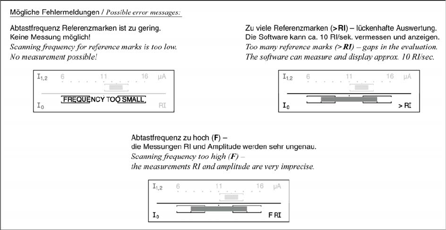
Gantry Settings 4.4.3 Checking Track Signals and Zero Pulse
268 Service Manual SIPLACE SX1/SX2/DX1/DX2 FS02
Settings
4.4.4 GCU (Up to Machine Nos.: Mxxx) Gantry Settings
Service Manual SIPLACE SX1/SX2/DX1/DX2 FS02 269
4.4.4
4.4.4 GCU (Up to Machine Nos.: Mxxx)
GCU (Up to Machine Nos.: Mxxx)
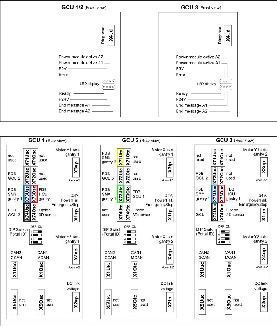
GCU - front side
GCU - rear side
Settings
Gantry Settings 4.4.5 Calibrating the X Axis
270 Service Manual SIPLACE SX1/SX2/DX1/DX2 FS02
4.4.5
4.4.5 Calibrating the X Axis
Calibrating the X Axis
Overview
The control parameters for the X axis depend, for example, on the installation site, frame and head types.
The parameters therefore need to be calibrated on site.
Procedure
4.4.6
4.4.6 Calibrating the Y Axis
Calibrating the Y Axis
Overview
The SX1/SX2/DX1/DX2 machines use "H gantries" for the Y axis. These consist of two opposite drives
with their own control and an encoder (scale and read unit). For correct position regulation, encoder cal-
ibration must be performed on initial operation and after any modifications.
Procedure
► Switch over to the operator level Service (Customer).
► Switch over to the Service menu and select Ma-
chine calibration.
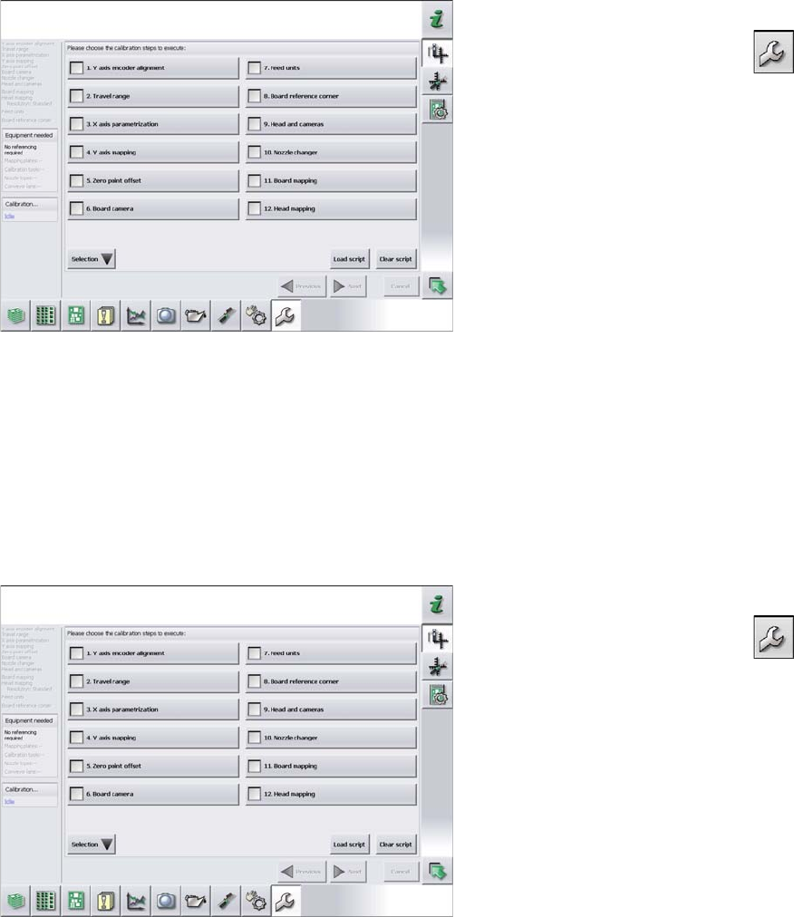
► Select 3. X axis parameterization and click on Next.
► Switch over to the operator level Service (Customer).
► Switch over to the Service menu and select Ma-
chine calibration.
► Select 1. Y axis encoder alignment and click on Next.
► Now perform machine calibration, including mapping.