00196497-07_SM_SXDX12_en.pdf - 第27页
Overview of the Modules 2.4.4 Width Adjustment CPP Service Manual SIPLACE SX1/SX2/DX1/DX2 FS02 27 2.5 2 . 5 C P P CPP 2.6 2 . 6 C & P 2 0 , C & P 2 0 A a n d C & P 2 0 M C&P20, C&P20 A and C&P20 M…
Overview of the Modules
Modular PCB Conveyor System 2.4.4 Width Adjustment
26 Service Manual SIPLACE SX1/SX2/DX1/DX2 FS02
Function Description
The width is adjusted by means of a motor as programmed. For dual conveyor systems, differing widths
can be set for the two conveyor lanes. The width adjustment uses a motor with its own measuring sys-
tem, meaning that the PCB width can be set independently of other machine components (e.g. the Y
gantry).
The PCB width is adjusted using two width adjustment units, which are fitted in the input and output ar-
eas. These adjustment units are moved synchronously back and forth by the drive motor, with the help
of recirculating spindles and a toothed belt.
In the dual conveyor, the fixing pins are moved out to release the side clamp. At the same time, the side
is fixed to the adjustment unit. After reaching the new PCB width, both fixing pins move back in. The
conveyor side is then clamped again.
In the single conveyor, the flexible side is moved directly by the two recirculating spindles of the adjust-
ment units.
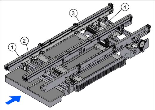
Width adjustment for dual conveyor
1. Adjustment unit
2. Recirculating spindle
3. Toothed belt of width adjustment
4. Drive unit of width adjustment
Overview of the Modules
2.4.4 Width Adjustment CPP
Service Manual SIPLACE SX1/SX2/DX1/DX2 FS02 27
2.5
2.5 CPP
CPP
2.6
2.6 C&P20, C&P20 A and C&P20 M
C&P20, C&P20 A and C&P20 M
CPP
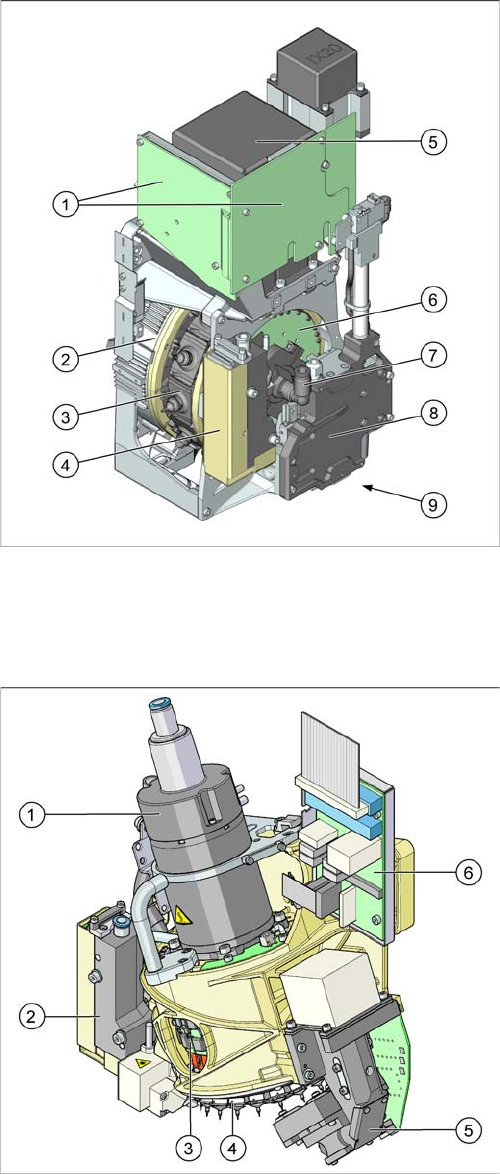
CPP with camera SST29 [03070108-xx]
CPP without camera [03053528-xx]
1. Intermediate distributor 1 and 2 (ID1, ID2)
2. Star motor (integrated in head housing)
3. DP axis (as direct drive)
4. Pressure control valve
5. Component camera (behind the intermediate distrib-
utor, standard: SST29)
6. Single core solution (SCS) – DP drive control
7. Holding circuit supply, integrated venturi nozzles and
valve assembly (valve terminal)
8. Z axis with return cylinder
9. Component sensor in the pick and place position (on
the underside)
C&P20 A
1. Star motor
2. Pressure control valve
3. DP drives (20 x)
4. Star with 20 nozzles
5. Component Camera
6. Intermediate distributor board

Overview of the Modules
C&P20, C&P20 A and C&P20 M 2.6.1 Differentiation of the C&P20 Head Variants
28 Service Manual SIPLACE SX1/SX2/DX1/DX2 FS02
2.6.1
2.6.1 Differentiation of the C&P20 Head Variants
Differentiation of the C&P20 Head Variants
Differenc es between CP 20/A/M
The C&P20A differs from the C&P20 in the following issues:
▪ New E/D transformer
▪ Improved linear guide rails at the segments
▪ Driver bearing
▪ Modified Z-axis (also used in C&P20 later on)
▪ Hoses
▪ FHE components
The C&P20M differs from the C&P20A in the following issue:
▪ Incremental encoder of the star motor
NOTICE
C&P20, C&P20A, C&P20M
The instructions apply in principle to all C&P20, C&P20A and C&P20M heads.
Any differences will be explicitly indicated.
► The different heads can be recognized according to the labeled stickers.