00196497-07_SM_SXDX12_en.pdf - 第271页
Settings 4.5.1 Setting the Nozzle Changer Height (DLM, C &P20, CPP, TH) No zzle Changer Setting Service Manual SIPLACE SX1/SX2/DX1/DX2 FS02 271 4.5 4 . 5 N o z z le C h a n g e r S e t t in g Nozzle Changer Setting 4…
Settings
Gantry Settings 4.4.5 Calibrating the X Axis
270 Service Manual SIPLACE SX1/SX2/DX1/DX2 FS02
4.4.5
4.4.5 Calibrating the X Axis
Calibrating the X Axis
Overview
The control parameters for the X axis depend, for example, on the installation site, frame and head types.
The parameters therefore need to be calibrated on site.
Procedure
4.4.6
4.4.6 Calibrating the Y Axis
Calibrating the Y Axis
Overview
The SX1/SX2/DX1/DX2 machines use "H gantries" for the Y axis. These consist of two opposite drives
with their own control and an encoder (scale and read unit). For correct position regulation, encoder cal-
ibration must be performed on initial operation and after any modifications.
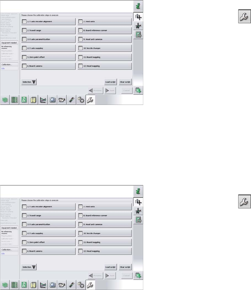
Procedure
► Switch over to the operator level Service (Customer).
► Switch over to the Service menu and select Ma-
chine calibration.
► Select 3. X axis parameterization and click on Next.
► Switch over to the operator level Service (Customer).
► Switch over to the Service menu and select Ma-
chine calibration.
► Select 1. Y axis encoder alignment and click on Next.
► Now perform machine calibration, including mapping.
Settings
4.5.1 Setting the Nozzle Changer Height (DLM, C&P20, CPP, TH) Nozzle Changer Setting
Service Manual SIPLACE SX1/SX2/DX1/DX2 FS02 271
4.5
4.5 Nozzle Changer Setting
Nozzle Changer Setting
4.5.1
4.5.1 Setting the Nozzle Changer Height (DLM, C&P20, CPP, TH)
Setting the Nozzle Changer Height (DLM, C&P20, CPP, TH)
Parts, equipment and tools
▪ NC shim plate [03021079-xx]
▪ NC support plate [03021044-xx]
▪ Screws DIN 965-M4 x 10-4.8 [00095312-xx]
Setting
4.5.2
4.5.2 Setting the Height of the Nozzle Reject Station (DLM, C&P20, CPP)
Setting the Height of the Nozzle Reject Station (DLM, C&P20, CPP)
Parts, equipment and tools
▪ Shim plates for nozzle reject device [03039514-xx]
Setting
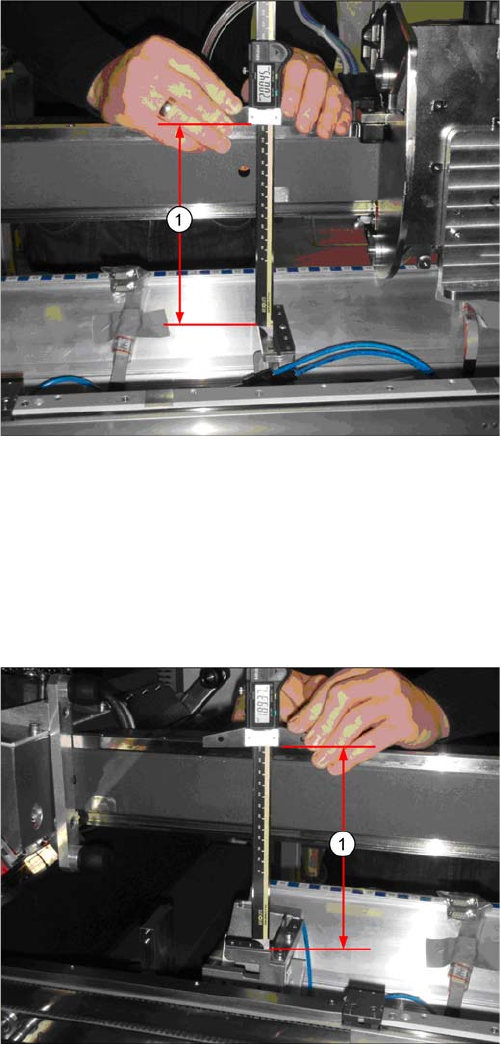
► The distance (1) between the contact surface of the
reject unit and the guide rail of the gantry needs to be
199.8 +/-0.2 mm.
You may need to use shim plates to adjust this.
► The distance (1) between the contact surface of the
nozzle reject station and the guide rail of the gantry
needs to be 189 +0.1/-0.3 mm.
You may need to use shim plates to adjust this.
Settings
Nozzle Changer Setting 4.5.3 Jumpers on the Nozzle Changer
272 Service Manual SIPLACE SX1/SX2/DX1/DX2 FS02
4.5.3
4.5.3 Jumpers on the Nozzle Changer
Jumpers on the Nozzle Changer
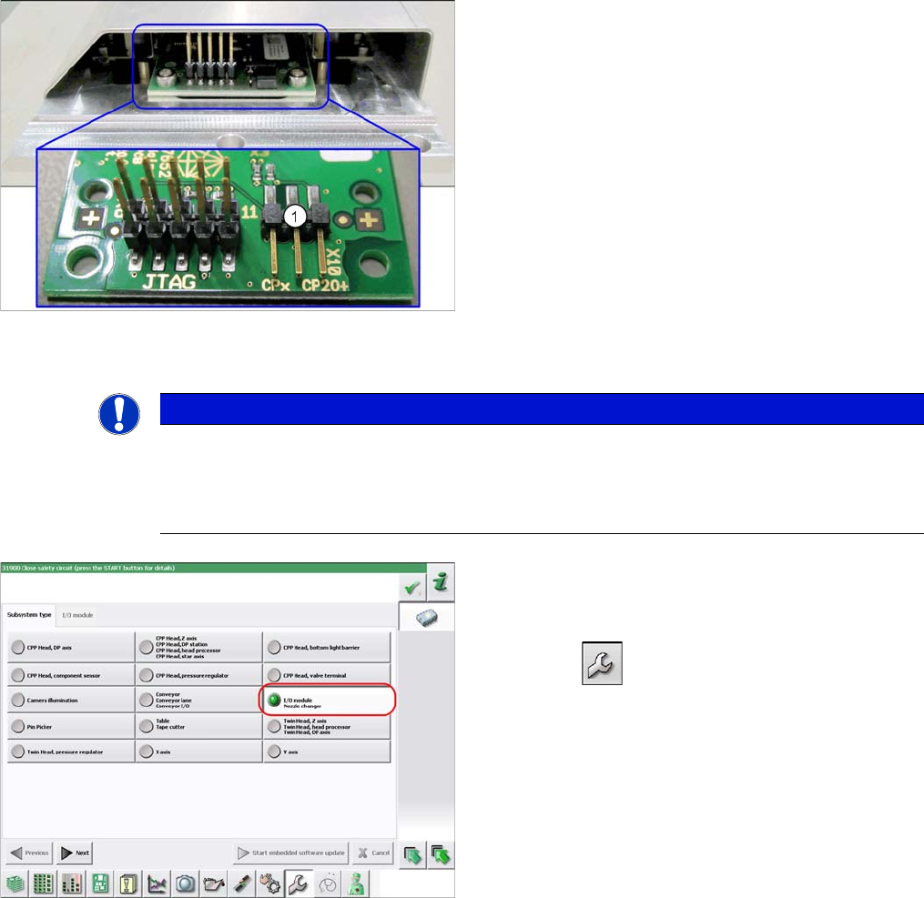
Overview
Preparation
1. Jumper X10
The jumper X10 needs to be set at the following nozzle
changers:
▪ Nozzle changer basic structure CPx/all assembly -
short [03103649-xx]
▪ Nozzle changer basic structure CPx/all assembly -
long [03103514-xx]
NOTICE
Before installation
Due to the design, this setting must be performed before installation in the machine.
► If the new nozzle changer is being fitted as a spare part in a machine with I/O module con-
trol, you will need to reconnect the jumper to pin 1-2.
To check whether the machine has I/O module control,
proceed as follows:
► Switch over to the operator level Service.
► Select the button.
► Select the button Embedded Software.
► Select the button Update Subsystem.
► If I/O module control is present, you will see the entry
Nozzle Changer at I/O Module.