00196497-07_SM_SXDX12_en.pdf - 第279页
Settings 4.6.2 Teaching the Sonar Sensor Conveyor Settings Service Manual SIPLACE SX1/SX2/DX1/DX2 FS02 279 ► To teach, press the button on the programming cable for approx. three seconds, until the LED on the sensor begi…
Settings
Conveyor Settings 4.6.2 Teaching the Sonar Sensor
278 Service Manual SIPLACE SX1/SX2/DX1/DX2 FS02
4.6.2
4.6.2 Teaching the Sonar Sensor
Teaching the Sonar Sensor
Parts, tools and equipment
▪ Setting gauge for ultrasonic sensors [03076989-xx]
▪ Programming cable for PXS240 sensor [03073330-xx]
This programming cable can be used for the following sonar sensors:
– Sonar sensor PXS240 [03069863-xx]
– Sonar sensor UB100-F77 [03089004Sxx]
Setting
► Use the software to move the conveyor sides into the position which allows you best access. Alter-
natively, you can also loosen the conveyor side clamps on the dual conveyor (see "3.6.1 Loosening
the Conveyor Side Clamps" [ ➙ 143]).
► Secure the machine by attaching relevant warning tags. Do not switch the machine off as the setting
would then not be applied. Observe the instructions in section "1.2 Preparatory Work..." [ ➙ 13].
NOTICE
2 versions of the programming cable
In the meantime, a second version of the programming cable (UB-PROG2) has been supplied.
The function of this programming cable is similar to that of programming cable PXS240. Fur-
thermore, two adapter cables (M8/M12 adapter and M12/M8 adapter) can be connected for the
sensor and the conveyor control cable.
The previous programming cable will now be available under the name "UB-PROG4-V31" (old
name was PXS240) and the item no.: [03073330-xx].
► See alsoProgramming Cable for PXS240 Sensor [03073330-xx]
► To use the new programming cable, proceed as follows:
Switch on the machine and place the gauge onto the conveyor, as described. To teach,
press the "A1" button on the programming cable for approx. three seconds, until the LED
on the sensor begins to flash. The "A2" button on the UB-PROG2 is not needed.
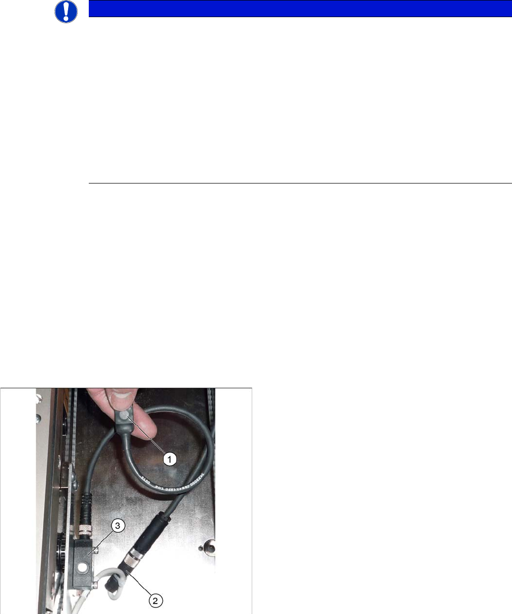
Connecting the programming cable (example of X4I
shown)
1. Programming cable
2. Press-fit connection for the ultrasonic sensor
3. Sonar sensor
► Unplug the press-fit connection from the ultrasonic
sensor and connect the programming cable between
this and the ultrasonic sensor.
Settings
4.6.2 Teaching the Sonar Sensor Conveyor Settings
Service Manual SIPLACE SX1/SX2/DX1/DX2 FS02 279
► To teach, press the button on the programming cable for approx. three seconds, until the LED on the
sensor begins to flash.
The switching threshold is set accordingly.
► Remove the setting gauge.
► Loosen the programming cable connections and reconnect the ultrasonic sensor directly to the con-
nection at the machine end.
See also
1.2 Preparatory Work... [ ➙ 13]
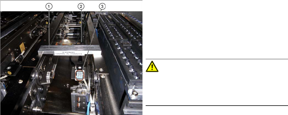
Fitted ultrasonic sensor with programming cable and ad
-
justment gauge (example of X4I shown)
1. Setting gauge
2. Programming cable (fitted)
3. LED on ultrasonic sensor
► The distance to the PCB is defined with the setting
gauge.
Position the setting gauge over the conveyor, so that
it is above the reception area of the ultrasonic sensor.
CAUTION!
Make sure that the gauge is used the right way round.
The gauges can be used for different conveyor types.
Make sure that the gauges are always used the right way
round.
▪ 3mm gap for the X conveyor
▪ 2mm gap for the SX conveyor
Settings
Conveyor Settings 4.6.3 Setting the Fixed Conveyor Side
280 Service Manual SIPLACE SX1/SX2/DX1/DX2 FS02
4.6.3
4.6.3 Setting the Fixed Conveyor Side
Setting the Fixed Conveyor Side
4.6.3.1
4.6.3.1 Setting the Fixed Conveyor Side on Single Conveyors
Setting the Fixed Conveyor Side on Single Conveyors
Parts, equipment and tools
▪ Dowel pin (supplied with conveyor) [03064582-xx]
Overview
Setting
► Use the software to move the flexible conveyor side into the position which allows you best access.
► Switch off the machine, disconnect it from the power supply and secure it to prevent unauthorized
reactivation. Observe the instructions in section "1.2 Preparatory Work..." [ ➙ 13].
► Loosen the fastening screws on both sides of the conveyor.
► Move the conveyor side into the required position.
► Insert the dowel pin and the fastening screw in the new position and tighten the fastening screw.
Perform this step on both sides of the conveyor.
► Remove the dowel pin.
See also
3.6.1 Loosening the Conveyor Side Clamps [ ➙ 143]
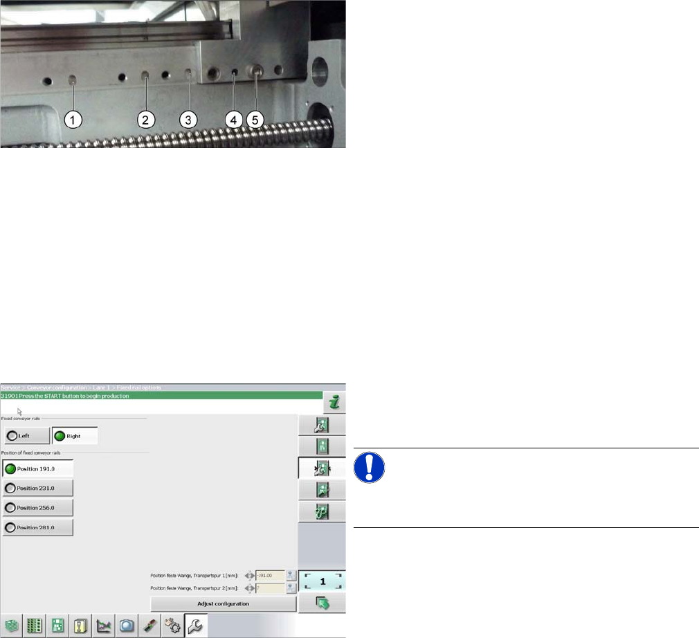
1. Printed circuit board 380 mm
2. Printed circuit board 460 mm (standard)
3. Printed circuit board 508 mm
4. Printed circuit board 560 mm
5. Fastening screw
The dowel pin is inserted at points (1) to (4):
► In the software set the fixed conveyor side and the
position (see "4.6.3.3 Conveyor Sides - Settings"
[ ➙ 282]).
NOTICE!
This menu is accessible from operator level Service (cus-
tomer)!