00196497-07_SM_SXDX12_en.pdf - 第282页
Settings Conveyor Settings 4.6.3 Setting the Fixed Conveyor Side 282 Service Manual SIPLACE SX1/SX2/DX1/DX2 FS02 4.6.3.3 4 . 6 . 3 . 3 C o n v e y o r S id e s - S e t t in g s Conveyor Sides - Settings The following dia…
Settings
4.6.3 Setting the Fixed Conveyor Side Conveyor Settings
Service Manual SIPLACE SX1/SX2/DX1/DX2 FS02 281
4.6.3.2
4.6.3.2 Setting the Fixed Conveyor Side on Dual Conveyors
Setting the Fixed Conveyor Side on Dual Conveyors
The fixed conveyor edge is always set with the software for dual conveyors.
Setting
► In the software set the fixed conveyor side and the
position (see "4.6.3.3 Conveyor Sides - Settings"
[ ➙ 282]).
NOTICE!
This menu is accessible from operator level Service (cus-
tomer)!
Settings
Conveyor Settings 4.6.3 Setting the Fixed Conveyor Side
282 Service Manual SIPLACE SX1/SX2/DX1/DX2 FS02
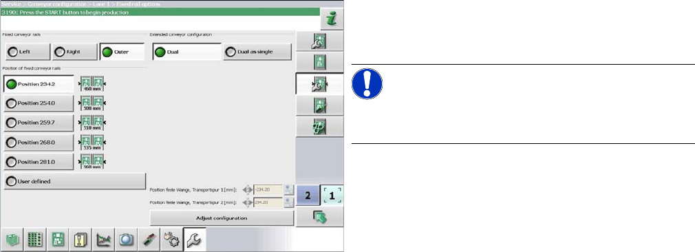
4.6.3.3
4.6.3.3 Conveyor Sides - Settings
Conveyor Sides - Settings
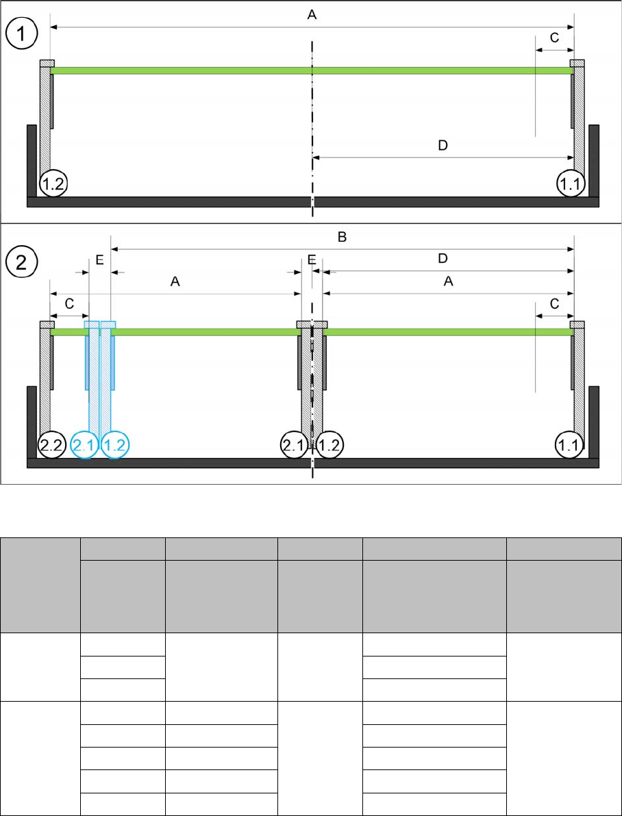
The following diagram shows a conveyor with the fixed conveyor side on the right. The same settings
apply to conveyors with the fixed side on the left.
View of a conveyor with a fixed side on the right (X-Series S as example)
SX1/SX2/DX1/DX2
SX1/SX2/DX1/DX2
* Dual conveyor FS02 with fixed side left: minimum PCB width 100 mm
A B C D E
Maximum
PCB width
Dual as single
conveyor
(flex)
Minimum
PCB width
Position of fixed
conveyor side
(from the
conveyor center)
Minimum
side distance
side 1.2/2.1
Single con-
veyor
510 --- 50 mm 231 ---
535 256
560 281
Dual con-
veyor
215 413 50 mm * 234.2 35 mm
235 433 254
242 430 259.7
250 450 268
260 460 281
Settings
4.6.4 Setting the Parallelism of the Conveyor Sides Conveyor Settings
Service Manual SIPLACE SX1/SX2/DX1/DX2 FS02 283
4.6.4
4.6.4 Setting the Parallelism of the Conveyor Sides
Setting the Parallelism of the Conveyor Sides
4.6.4.1
4.6.4.1 Setting the Parallelism of the Adjustment Unit
Setting the Parallelism of the Adjustment Unit
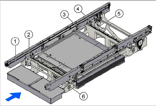
Overview
Setting
► Use the software to move the conveyor side into the position which allows you best access.
► Switch off the machine, disconnect it from the power supply and secure it to prevent unauthorized
reactivation. Observe the instructions in section "1.2 Preparatory Work..." [ ➙ 13].
► Loosen the screws fastening the width adjustment drive. The toothed belt of the width adjustment
should then have enough play so that you can move the width adjustment units independently of one
another. You may need to loosen the toothed belt from the deflection pulleys.
► Place the toothed belt over the two upper deflection pulleys so that the spindles move exactly parallel
to one another. Check the parallelism as follows:
► If you have loosened the toothed belt from the deflection pulleys, insert this again now.
► Push the spindles by hand outwards, to one side of the conveyor. Insert a spacer piece in each case.
This helps you to check the distance to the frame more easily. Make sure that the lifting table plate
guides are only lying against the spindle base structures and not against the threads.
1. Flexible conveyor side wall (shown on the left here)
2. Adjustment unit
3. Toothed belt of width adjustment
4. Adjustment unit
5. Width adjustment drive
6. Fixed conveyor side (shown on the right here)