00196497-07_SM_SXDX12_en.pdf - 第285页
Settings 4.6.4 Setting the Parallelism of the Conveyor Sides Conveyor Settings Service Manual SIPLACE SX1/SX2/DX1/DX2 FS02 285 4.6.4.2 4 . 6 . 4 . 2 S e t t in g t h e P a r a lle lis m o f t h e D u a l C o n v e y o r …
Settings
Conveyor Settings 4.6.4 Setting the Parallelism of the Conveyor Sides
284 Service Manual SIPLACE SX1/SX2/DX1/DX2 FS02
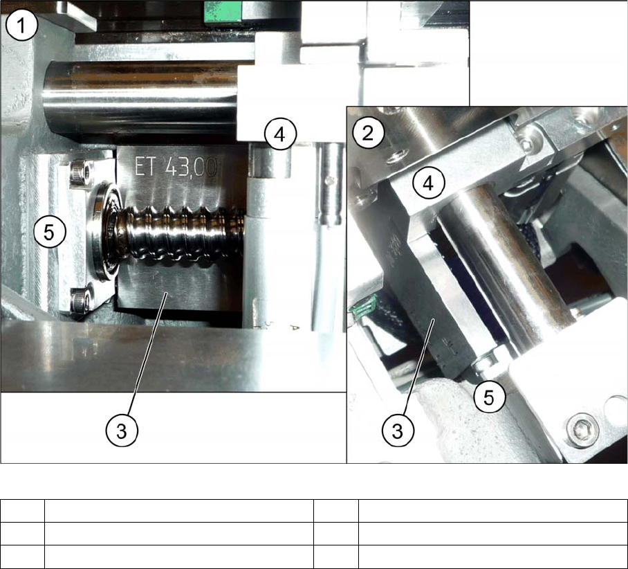
Setting the parallelism (example of DC shown)
► Tighten the screws fastening the drive again and set the belt tension to 20 +/-2 Hz. (see "4.6.1.3 Set-
ting the Tension of the Width Adjustment Toothed Belt" [ ➙ 276]).
Verification
Check the parallelism of the conveyor sides.
► Measure and compare the distance of the spindles to the stops. The distance must be the same at
both spindles.
► Pull the toothed belt to move the spindles manually as far as the edge. The spindles must touch the
two stops at the same time.
► Calibrate the width adjustment motor (see "4.6.5 Calibrating the Motors in the Conveyor" [ ➙ 287]).
► Calibrate the conveyor width (see "4.6.6 Conveyor Width Calibration" [ ➙ 288]).
See also
4.6.5 Calibrating the Motors in the Conveyor [ ➙ 287]
1 View from the side 2 View from above
3 Spacer piece (here: metal platelet) 4 Adjustment unit
5Frame 6Bearing
Settings
4.6.4 Setting the Parallelism of the Conveyor Sides Conveyor Settings
Service Manual SIPLACE SX1/SX2/DX1/DX2 FS02 285
4.6.4.2
4.6.4.2 Setting the Parallelism of the Dual Conveyor Sides
Setting the Parallelism of the Dual Conveyor Sides
Parts, equipment and tools
Setting
► If you unable to set the parallelism, contact your local SIPLACE Service team.
► Use the software to move the conveyor sides into the position which allows you best access. Alter-
natively, you can also loosen the conveyor side clamps on the dual conveyor (see "3.6.1 Loosening
the Conveyor Side Clamps" [ ➙ 143]).
► Switch off the machine, disconnect it from the power supply and secure it to prevent unauthorized
reactivation. Observe the instructions in section "1.2 Preparatory Work..." [ ➙ 13].
► Loosen the screws fastening the width adjustment drive. The toothed belt of the width adjustment
should then have enough play so that you can move the adjustment units independently of one an-
other. You may need to loosen the toothed belt from the deflection pulleys.
► Place the toothed belt over the two upper deflection pulleys so that the adjustment units move ex-
actly parallel to one another. Check the parallelism as follows:
► If you have loosened the toothed belt from the deflection pulleys, insert this again now.
► Push the adjustment units by hand outwards, to one side of the conveyor. Insert a spacer piece in
each case. This helps you to check the distance to the frame more easily. Make sure that the lifting
table plate guides are only lying against the adjustment unit base structures and not against the
threads.
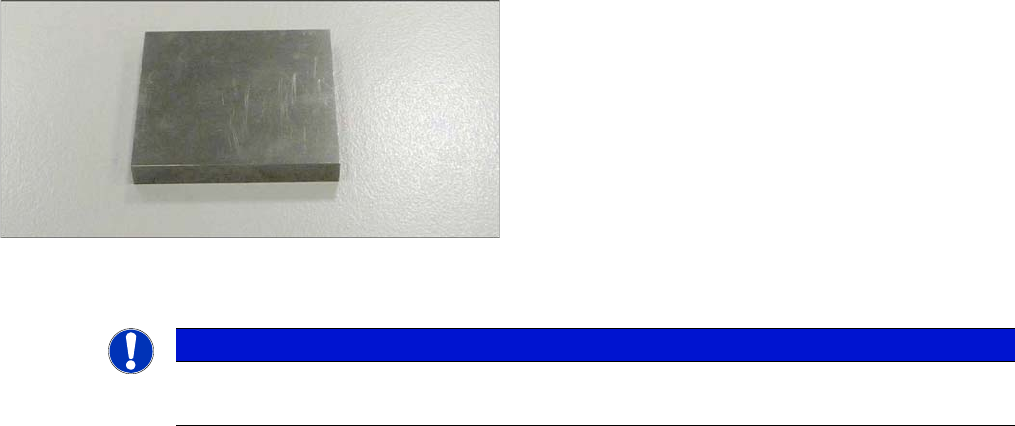
▪ To check the adjustment unit stoppers, you need two
suitably sized and identical pieces of metal (see be-
low).
You could also use two lifting table plate guides if
needed.
NOTICE
Adjustment units
The parallelism of the conveyor sides depends on the parallelism of the adjustment units.
Settings
Conveyor Settings 4.6.4 Setting the Parallelism of the Conveyor Sides
286 Service Manual SIPLACE SX1/SX2/DX1/DX2 FS02
► Tighten the screws fastening the drive again and set the belt tension to 20 +/-2 Hz. (see "4.6.1.3 Set-
ting the Tension of the Width Adjustment Toothed Belt" [ ➙ 276]).
► If the conveyor side clamps have loosened, fix these again.
Check
Check the parallelism of the conveyor sides.
► Measure and compare the distance of the adjustment units to the stops. The distance must be the
same at both adjustment units.
► Pull the toothed belt to move the adjustment units manually as far as the edge. The adjustment units
must touch the two stops at the same time.
► Calibrate the width adjustment motor (see "4.6.5 Calibrating the Motors in the Conveyor" [ ➙ 287]).
► Displace the fixed conveyor side wall. This ensures that the fixed conveyor side is parallel to the flex-
ible sides. Readjust the fixed conveyor side to its original value after that.
► Calibrate the conveyor width (see "4.6.6 Conveyor Width Calibration" [ ➙ 288]).
See also
4.6.5 Calibrating the Motors in the Conveyor [ ➙ 287]
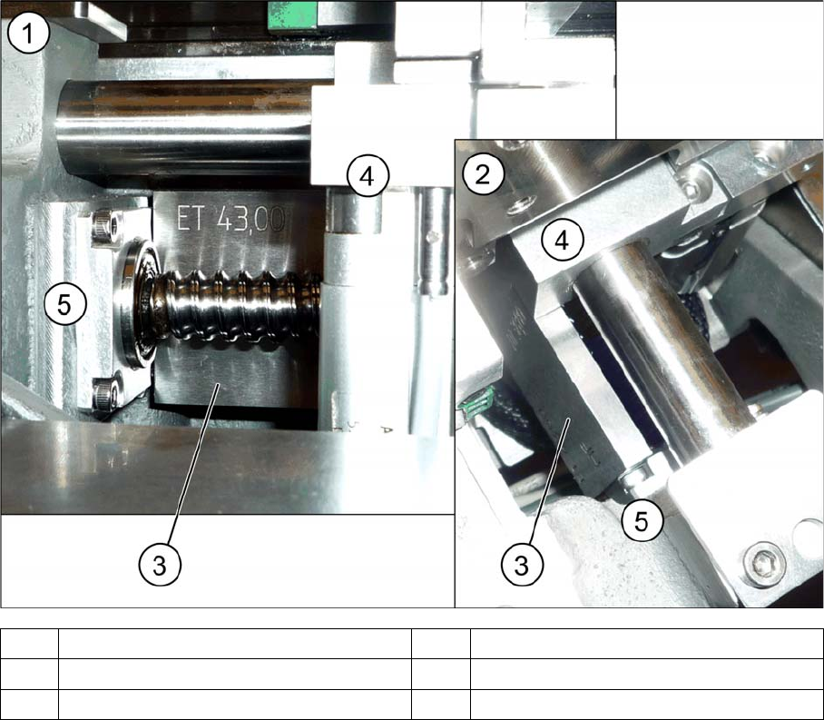
1 View from the side 2 View from above
3 Spacer piece (here: metal platelet) 4 Adjustment unit
5Frame 6Bearing