00196497-07_SM_SXDX12_en.pdf - 第290页
Settings Conveyor Settings 4.6.8 Lifting Table 290 Service Manual SIPLACE SX1/SX2/DX1/DX2 FS02 4.6.8 4 . 6 . 8 L if t in g T a b le Lifting Table 4.6.8.1 4 . 6 . 8 . 1 S e t t in g t h e P a r a lle lis m a n d H e ig h …
Settings
4.6.7 Board Clamping Conveyor Settings
Service Manual SIPLACE SX1/SX2/DX1/DX2 FS02 289
4.6.7
4.6.7 Board Clamping
Board Clamping
4.6.7.1
4.6.7.1 Setting the Board Clamping (Actuator)
Setting the Board Clamping (Actuator)
If the conveyor control issues the error Clamping error conveyor, you need to check the distance from
the lifting table actuator to the upper edge of the conveyor belt.
Parts, equipment and tools
▪ Setting gauge for actuator [03049740-xx]
▪ Terminal strip [03076699-xx]
Setting
► Fit the terminal strip onto the long side of the setting gauge.
► Loosen the screws fastening the actuator.
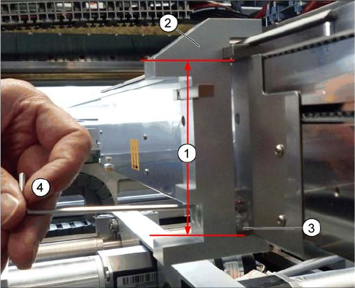
► Attach the setting gauge to the conveyor side, as shown in the diagram.
► Tighten the screws fastening the actuator. This sets the distance to 94.0 mm.
► Repeat this setting at all actuators.
1. Distance of 94.0 mm from the lower edge of the actu-
ator to the upper edge of the conveyor toothed belt
2. Setting gauge
3. Actuator.
4. Loosen and tighten the screws fastening the actuator
through the hole provided in the gauge.
Settings
Conveyor Settings 4.6.8 Lifting Table
290 Service Manual SIPLACE SX1/SX2/DX1/DX2 FS02
4.6.8
4.6.8 Lifting Table
Lifting Table
4.6.8.1
4.6.8.1 Setting the Parallelism and Height of the Lifting Table Plate
Setting the Parallelism and Height of the Lifting Table Plate
Overview
Setting
► Use the software to move the conveyor sides to maximum width. (See "3.6.1 Loosening the Convey-
or Side Clamps" [ ➙ 143])
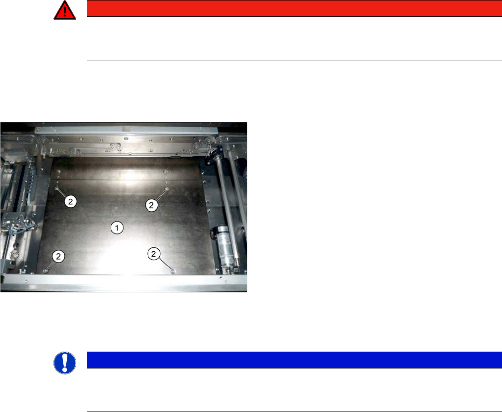
► Loosen the screws fastening the lifting table plate but do not remove the lifting table plate.
► Use the software to clamp the lifting table (without board).
► Underneath the fastening screws, there are setting screws (socket-head 5). Use these setting
screws to set the lifting table plate so that it has no play between it and the clamping edge.
► Check all four corners of the lifting table for any play.
► Check the setting by clamping a board into place. Check all corners to see whether there is any play.
► Calibrate the zero position of the lifting table motor.
See also
4.6.5 Calibrating the Motors in the Conveyor [ ➙ 287]
1.2 Preparatory Work... [ ➙ 13]
DANGER
Press the EMERGENCY STOP!
Before performing adjustment work you must ensure that the lifting table has been secured
against movement!
Lifting table plate (example of SX1/SX2 V2 shown)
1. Lifting table plate
2. Fastening screws for lifting table plate
NOTICE
Single, dual conveyor
The setting is shown in the diagram using the example of a lifting table unit for the dual conveyor
(DC). Setting the single conveyor (SC) follows the same procedure.
Settings
4.7.1 Times for Setting the Throttle on the Cutter (From SW707.1) Settings on the Cutter
Service Manual SIPLACE SX1/SX2/DX1/DX2 FS02 291
4.7
4.7 Settings on the Cutter
Settings on the Cutter
4.7.1
4.7.1 Times for Setting the Throttle on the Cutter (From SW707.1)
Times for Setting the Throttle on the Cutter (From SW707.1)
NOTICE!
From SW707.1
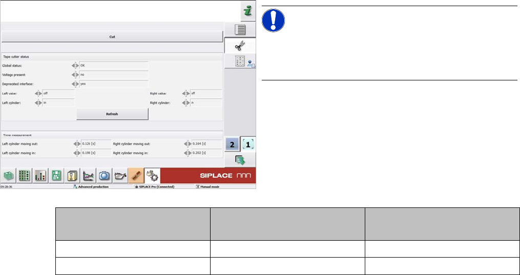
From software version 707.1, the throttle times on the
cutter are displayed in the station software.
Cutter SX1/SX2, DX1/DX2
[03063781-xx]
X-Series S
[03066690-xx]
Moving the balde out 160 to 220 ms 175 to 200 ms
Moving the blade in 210 to 230 ms 200 to 250 ms