00196497-07_SM_SXDX12_en.pdf - 第293页
Settings 4.9.1 Firmware Download (SW 70x) Other Settings Service Manual SIPLACE SX1/SX2/DX1/DX2 FS02 293 4.9 4 . 9 O t h e r S e t t in g s Other Settings 4.9.1 4 . 9 . 1 F ir m w a r e D o w n lo a d ( S W 7 0 x ) Firmw…
Settings
Settings on the Component Trolley 4.8.1 Setting the Changeover Table Height
292 Service Manual SIPLACE SX1/SX2/DX1/DX2 FS02
4.8
4.8 Settings on the Component Trolley
Settings on the Component Trolley
4.8.1
4.8.1 Setting the Changeover Table Height
Setting the Changeover Table Height
4.8.1.1
4.8.1.1 Adjusting the Changeover Table to the Board Transport Height
Adjusting the Changeover Table to the Board Transport Height
4.8.1.2
4.8.1.2 Adjusting the Changeover Table Height to the Machine
Adjusting the Changeover Table Height to the Machine
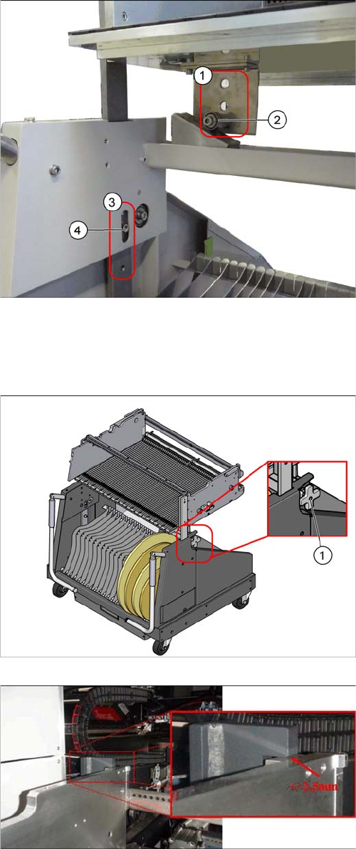
Changeover table with a board transport height of
950 mm
► Loosen the screws (4) for the top and bottom stop-
pers.
► Lift the changeover table plate. You may need to en-
list the help of a second person for this.
► Loosen the pulleys (2) and screw these tight again at
the required height:
⇨ 900 mm ± 15 mm SMEMA height
⇨ 930 mm ± 15 mm SMEMA height
⇨ 950 mm ± 15 mm SMEMA height
These heights correspond with the holes (1) (from top to
bottom).
► Insert the screws (4) for the top and bottom stoppers
in the corresponding holes (3).
1. Height adjustment wheel.
► To adjust the height to the COT insert, push the
changeover table into the machine until the stopper
block of the table is positioned under the bracket of
the table height check.
► Use the adjustment wheel to lift the changeover table
until the surfaces are almost but not quite touching.
The tolerance between the function surfaces is +/
- 2.5 mm.
Settings
4.9.1 Firmware Download (SW 70x) Other Settings
Service Manual SIPLACE SX1/SX2/DX1/DX2 FS02 293
4.9
4.9 Other Settings
Other Settings
4.9.1
4.9.1 Firmware Download (SW 70x)
Firmware Download (SW 70x)
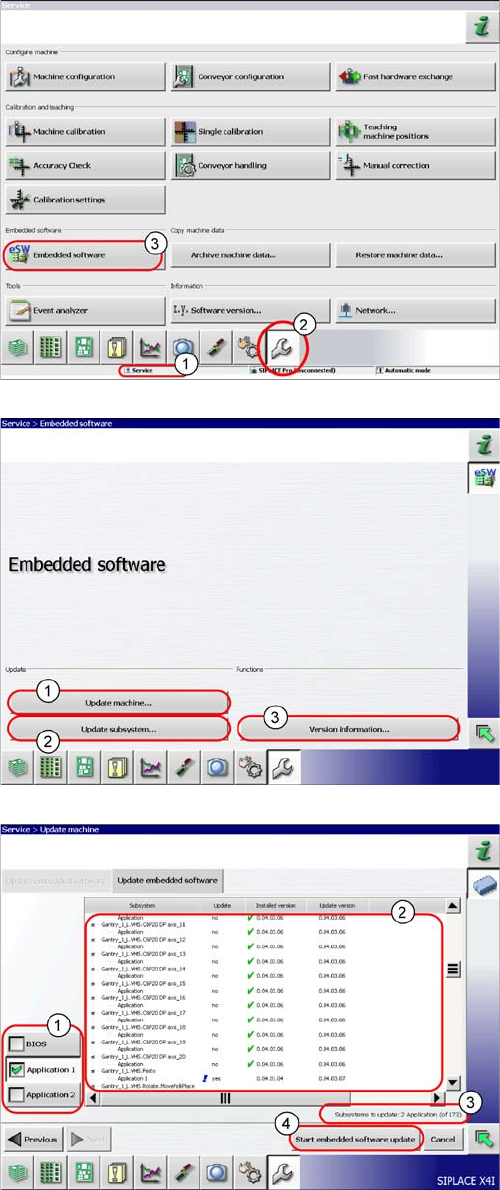
► The function Firmware Download can be performed
with the operator levels (1) Machine-Service or
SIPLACE-Service.
► Switch over to the service menu (2).
► Select the button Embedded Software (3).
► (1) Select this button to check the entire machine and
to perform an eSW download for multiple subsys-
tems.
► (2) Select this button to select and check one subsys-
tem, to perform an eSW download.
► (3) Select this button to view all versions of the sub-
systems, BIOS application 1/2.
1. Selection button, BIOS application 1/2
2. Shows the status of the individual subsystems.
3. Update information about the number of subsystems
which still have to be downloaded.
4. Starts the download.
Settings
Other Settings 4.9.2 Calibration
294 Service Manual SIPLACE SX1/SX2/DX1/DX2 FS02
4.9.2
4.9.2 Calibration
Calibration
Overview
This calibration step first measures the component camera. This determines the relationship of "camera
pixel size to resolution of machine measuring system (X,Y)", the "camera center point in X and Y direc-
tion" and the "torsion angle of the CCD sensor in the camera". This is following by determining the head
offset and the segment offsets for the top and bottom.
▪ Head offset: the head offset is the distance between the PCB camera and the nozzle (segment 1).
The target is a fixed value (X=0 and Y=-105 mm), to which an offset value (from the head calibration)
is added.
▪ Segment offset top: the top segment offset involves turning the calibration tool in the component
camera in 0, 90, 180 and 270° steps. The value determined is that of the rotating center of the nozzle
tip in relation to the component camera center in the X and Y direction.
▪ Segment offset bottom: the bottom segment offset involves recording and measuring the calibration
tool in the 0, 90, 180 and 270° positions. The value determined is that of the rotating center point of
the nozzle tip when the Z axis is extended in relation to the PCB camera. Segment 1 forms the ref-
erence (X=0, Y=0) to the other segments.
4.9.2.1
4.9.2.1 Calibrating the Heads and Cameras (SW60x)
Calibrating the Heads and Cameras (SW60x)
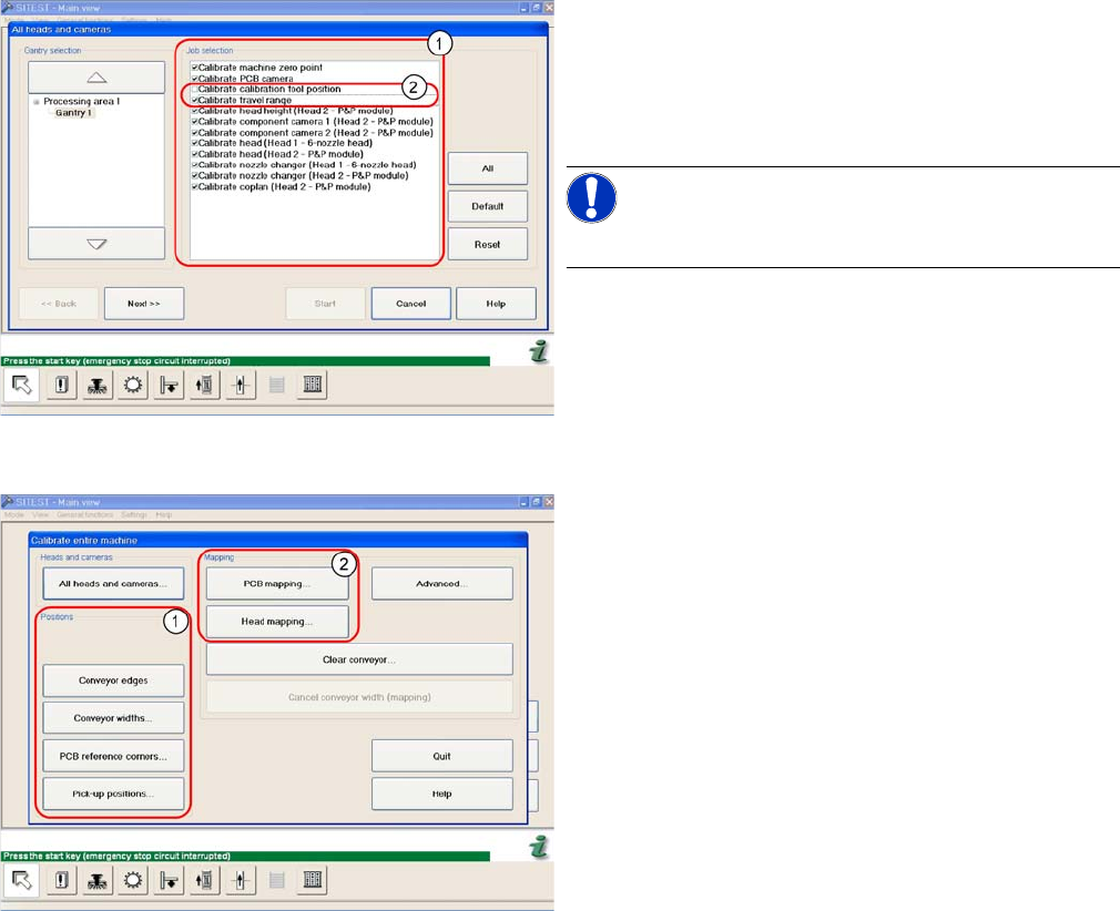
Automatic calibration of all heads and cameras
The menu may vary, according to the machine type and
configuration.
► Go to SITEST and select Calibrate Entire Machine --
> All Heads and Cameras to access the adjacent
menu.
► Go to the section Job Selection (1) and select the
components to be calibrated.
NOTICE!
These two entries (2) are optional.
► To continue calibration with manual handling, select
the four consecutive menus in from the section Posi-
tions (1) and the two menu items from the section
Mapping (2).