00196497-07_SM_SXDX12_en.pdf - 第295页
Settings 4.9.2 Calibration Other Settings Service Manual SIPLACE SX1/SX2/DX1/DX2 FS02 295 4.9.2.2 4 . 9 . 2 . 2 C a lib r a t in g t h e H e a d s a n d C a m e r a s ( S W 7 0 x ) Calibrating the Heads and Cameras (SW70…
Settings
Other Settings 4.9.2 Calibration
294 Service Manual SIPLACE SX1/SX2/DX1/DX2 FS02
4.9.2
4.9.2 Calibration
Calibration
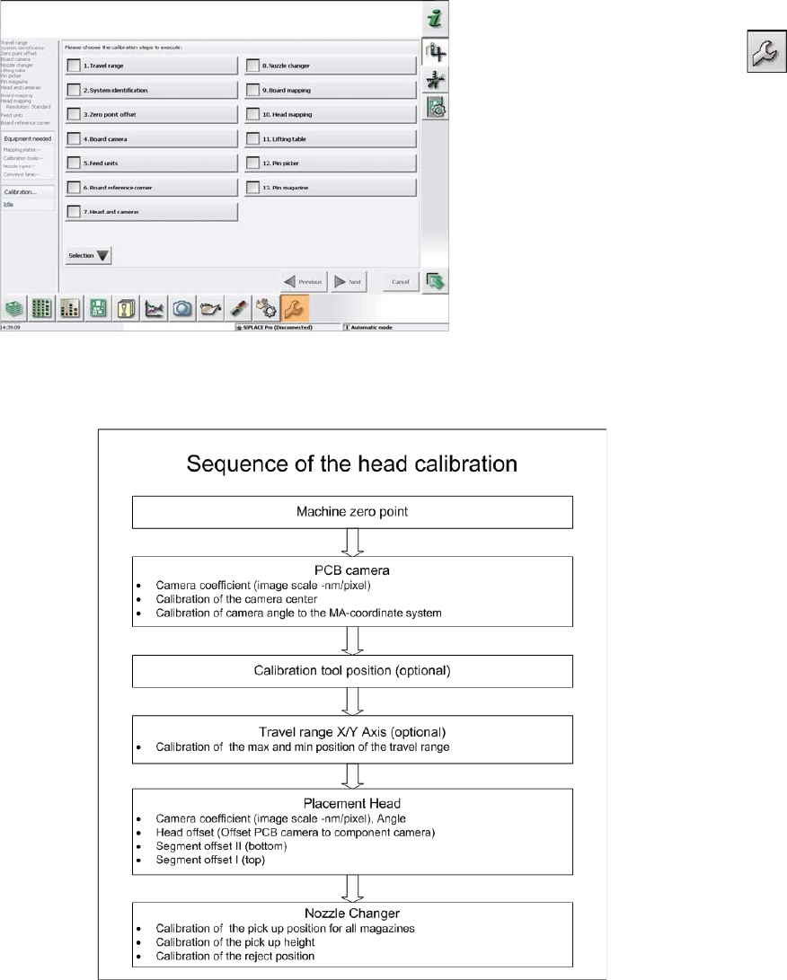
Overview
This calibration step first measures the component camera. This determines the relationship of "camera
pixel size to resolution of machine measuring system (X,Y)", the "camera center point in X and Y direc-
tion" and the "torsion angle of the CCD sensor in the camera". This is following by determining the head
offset and the segment offsets for the top and bottom.
▪ Head offset: the head offset is the distance between the PCB camera and the nozzle (segment 1).
The target is a fixed value (X=0 and Y=-105 mm), to which an offset value (from the head calibration)
is added.
▪ Segment offset top: the top segment offset involves turning the calibration tool in the component
camera in 0, 90, 180 and 270° steps. The value determined is that of the rotating center of the nozzle
tip in relation to the component camera center in the X and Y direction.
▪ Segment offset bottom: the bottom segment offset involves recording and measuring the calibration
tool in the 0, 90, 180 and 270° positions. The value determined is that of the rotating center point of
the nozzle tip when the Z axis is extended in relation to the PCB camera. Segment 1 forms the ref-
erence (X=0, Y=0) to the other segments.
4.9.2.1
4.9.2.1 Calibrating the Heads and Cameras (SW60x)
Calibrating the Heads and Cameras (SW60x)
Automatic calibration of all heads and cameras
The menu may vary, according to the machine type and
configuration.
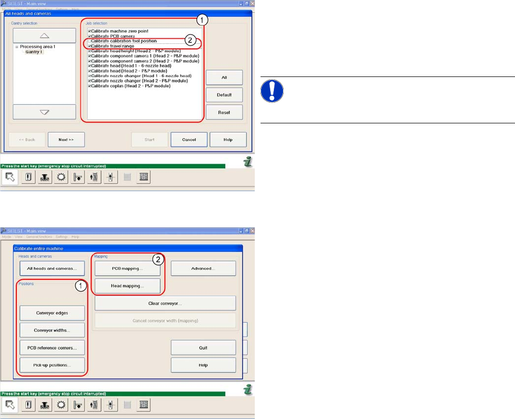
► Go to SITEST and select Calibrate Entire Machine --
> All Heads and Cameras to access the adjacent
menu.
► Go to the section Job Selection (1) and select the
components to be calibrated.
NOTICE!
These two entries (2) are optional.
► To continue calibration with manual handling, select
the four consecutive menus in from the section Posi-
tions (1) and the two menu items from the section
Mapping (2).
Settings
4.9.2 Calibration Other Settings
Service Manual SIPLACE SX1/SX2/DX1/DX2 FS02 295
4.9.2.2
4.9.2.2 Calibrating the Heads and Cameras (SW70x)
Calibrating the Heads and Cameras (SW70x)
4.9.2.3
4.9.2.3 Calibration Procedure
Calibration Procedure
C&P calibration procedure
Automatic calibration (SW707)
► Switch over to the operator level Service (Customer).
► Switch over to the Service menu and select Ma-
chine calibration or Automatic calibration (depending
on SW version).
► Select Head and cameras and click on Next.
► On the next page, select the gantries on which the
heads to be calibrated are located and then click on
Next.
► The next step is to check the calibration conditions
(nozzle, calibration tool etc.). Follow the instructions
provided.
After this step, calibration will begin. All required interme-
diate steps (head height etc.) will be performed automat-
ically.
Settings
Other Settings 4.9.3 Setting the Nozzle Reject and Station Height
296 Service Manual SIPLACE SX1/SX2/DX1/DX2 FS02
4.9.3
4.9.3 Setting the Nozzle Reject and Station Height
Setting the Nozzle Reject and Station Height
Parts, equipment and tools
▪ Depth measuring gauge (300 mm) [03079617-xx]
▪ Adjusting plates for nozzle reject device [03039514-xx]
▪ Screws DIN 7991-M4 x 20-8.8 [00333782-xx]
▪ Plastic sheet (to keep the depth measuring gauge away from the magnets).
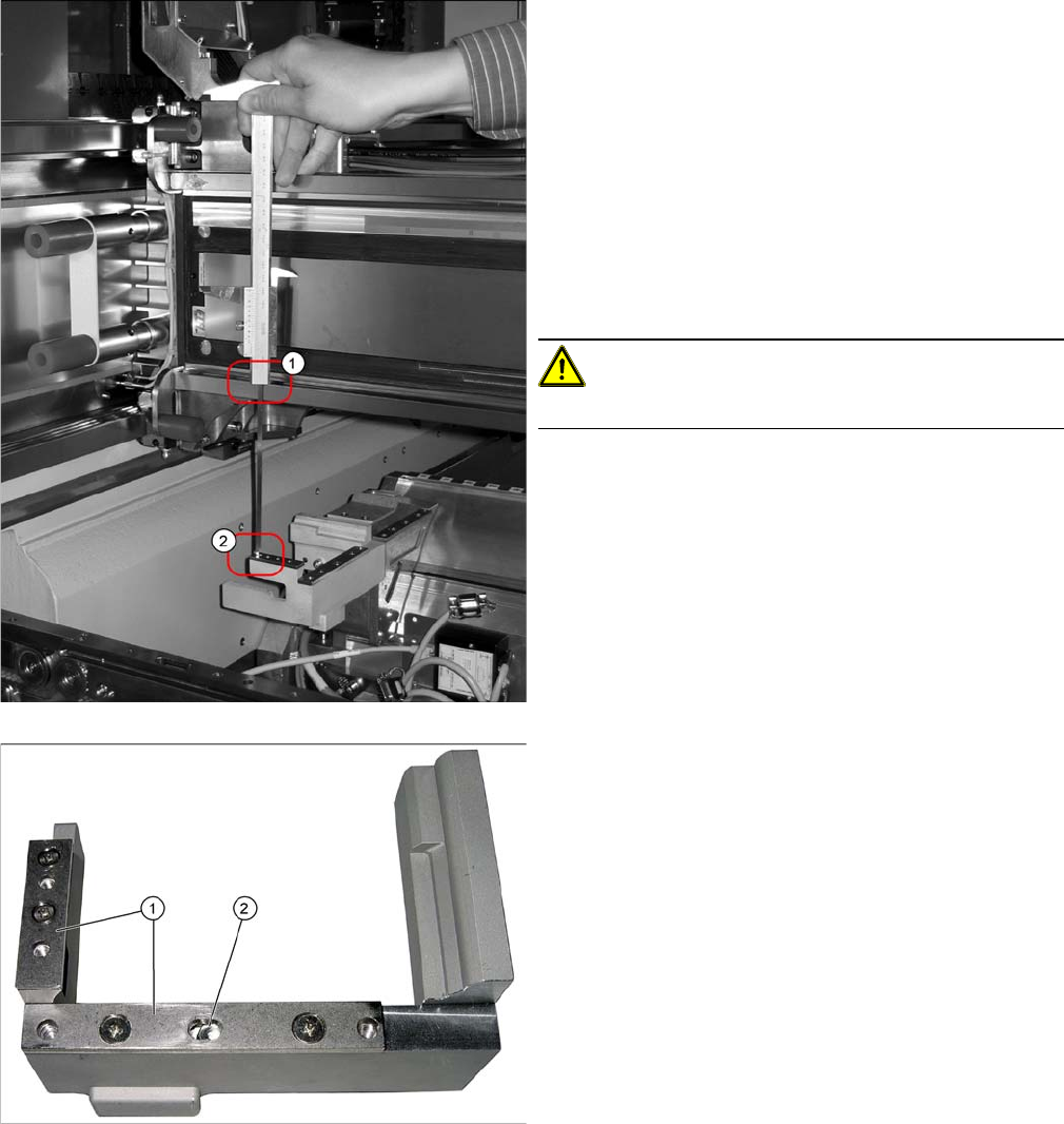
Setting
1. Position upper edge of measuring scale on the linear
guidance.
2. Bottom end of measuring gauge on the assembly sur-
face of the nozzle station
► Push the placement head to be measured outwards.
► Place a plastic plate in front of the magnets.
► Position the measuring gauge on the upper edge of
the nozzle station assembly surface and measure the
distance to the upper edge of the lower X axis linear
guidance.
CAUTION!
Hold the measuring scale vertically!
1. Adjusting plates
2. Slot
► Set a distance of 139.0±0.2 mm for all placement
heads.
If the distance is too large, insert shim plates: Shim
plates for nozzle stripping device [03039514-xx,
Screws DIN7991 M4x20-8.8 [00333782-xx].