00196497-07_SM_SXDX12_en.pdf - 第296页
Settings Other Settings 4.9.3 Setting the Nozzle Reject and Station Height 296 Service Manual SIPLACE SX1/SX2/DX1/DX2 FS02 4.9.3 4 . 9 . 3 S e t t in g t h e N o z z le R e je c t a n d S t a t io n H e ig h t Setting th…
Settings
4.9.2 Calibration Other Settings
Service Manual SIPLACE SX1/SX2/DX1/DX2 FS02 295
4.9.2.2
4.9.2.2 Calibrating the Heads and Cameras (SW70x)
Calibrating the Heads and Cameras (SW70x)
4.9.2.3
4.9.2.3 Calibration Procedure
Calibration Procedure
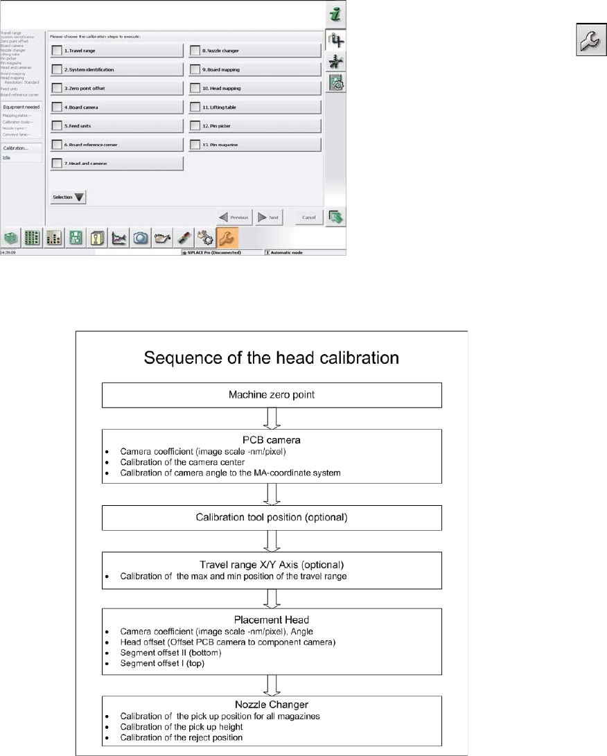
C&P calibration procedure
Automatic calibration (SW707)
► Switch over to the operator level Service (Customer).
► Switch over to the Service menu and select Ma-
chine calibration or Automatic calibration (depending
on SW version).
► Select Head and cameras and click on Next.
► On the next page, select the gantries on which the
heads to be calibrated are located and then click on
Next.
► The next step is to check the calibration conditions
(nozzle, calibration tool etc.). Follow the instructions
provided.
After this step, calibration will begin. All required interme-
diate steps (head height etc.) will be performed automat-
ically.
Settings
Other Settings 4.9.3 Setting the Nozzle Reject and Station Height
296 Service Manual SIPLACE SX1/SX2/DX1/DX2 FS02
4.9.3
4.9.3 Setting the Nozzle Reject and Station Height
Setting the Nozzle Reject and Station Height
Parts, equipment and tools
▪ Depth measuring gauge (300 mm) [03079617-xx]
▪ Adjusting plates for nozzle reject device [03039514-xx]
▪ Screws DIN 7991-M4 x 20-8.8 [00333782-xx]
▪ Plastic sheet (to keep the depth measuring gauge away from the magnets).
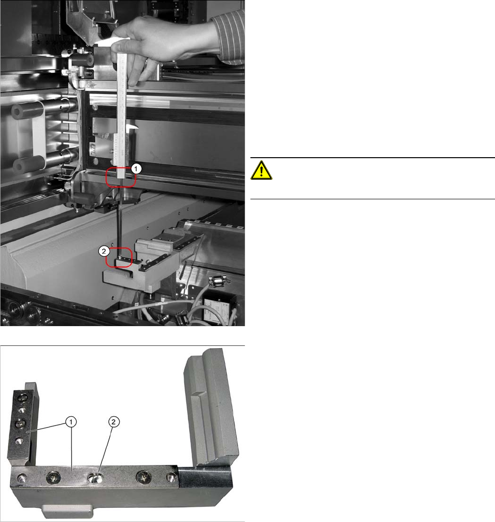
Setting
1. Position upper edge of measuring scale on the linear
guidance.
2. Bottom end of measuring gauge on the assembly sur-
face of the nozzle station
► Push the placement head to be measured outwards.
► Place a plastic plate in front of the magnets.
► Position the measuring gauge on the upper edge of
the nozzle station assembly surface and measure the
distance to the upper edge of the lower X axis linear
guidance.
CAUTION!
Hold the measuring scale vertically!
1. Adjusting plates
2. Slot
► Set a distance of 139.0±0.2 mm for all placement
heads.
If the distance is too large, insert shim plates: Shim
plates for nozzle stripping device [03039514-xx,
Screws DIN7991 M4x20-8.8 [00333782-xx].
Settings
4.9.4 DIP Switch for Camera Types 25 and 33 Other Settings
Service Manual SIPLACE SX1/SX2/DX1/DX2 FS02 297
4.9.4
4.9.4 DIP Switch for Camera Types 25 and 33
DIP Switch for Camera Types 25 and 33
Setting
► Switch off the machine, disconnect it from the power supply and secure it to prevent unauthorized
reactivation. Observe the instructions in section "1.2 Preparatory Work..." [ ➙ 13].
► Remove the camera upper part and the cover on the lower part, to gain access to the DIP switches.
► Set the DIP switches. (see below)
► Fit all parts by following the above instructions in the reverse order.
DIP switch
Boards with version status 01 and 02 are fitted with a TQ module. In this case, the DIP switching block
is 8 pin.
Boards with version status 03 or higher do not have a TQ module. In this case, the DIP switching block
is 6 pin.
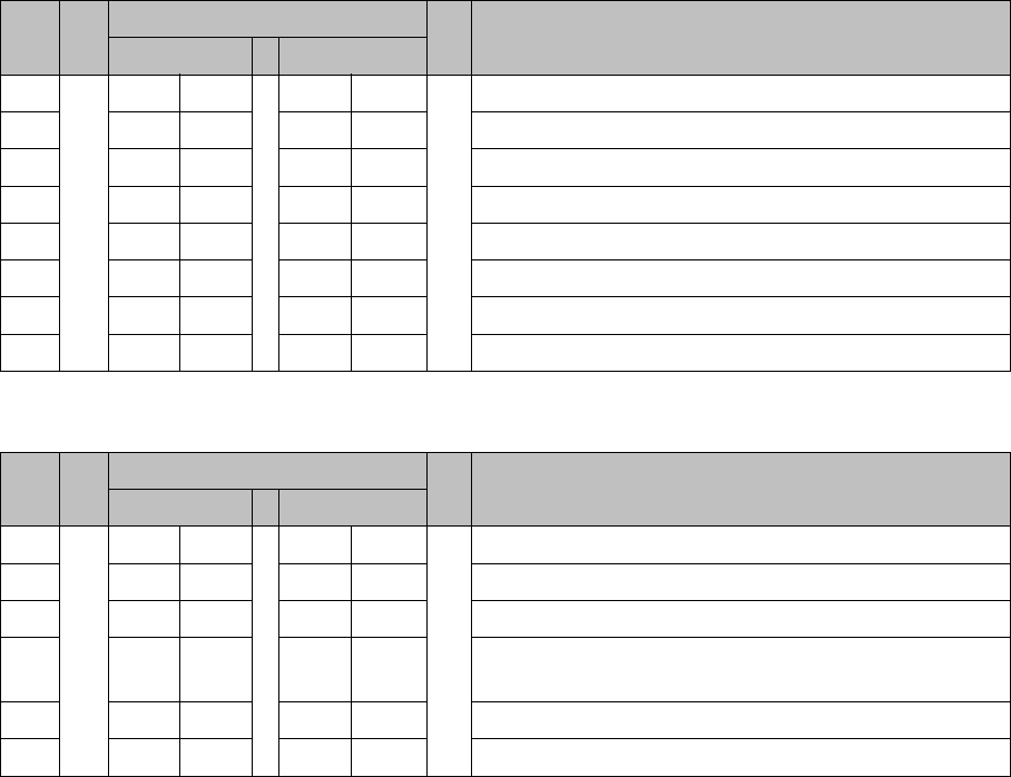
Version state 01 and 02: DIP switch settings (8 pin)
* Not all gantries may be available, depending on the machine type.
Version state 03 and higher: DIP switch settings (6 pin)
* Not all gantries may be available, depending on the machine type.
See also
5.6.1 Vision LED driver VLT 33 [03039244-xx] [ ➙ 331]
S Setting for gantry* Comments
1 2
1OFFOFFBootstrap
2OFFOFFReset
3OFFOFFGantry ID 0
4OFFONGantry ID 1
5OFFOFFTest
6OFFOFFCAN terminator
7ON ON CAN speed: ON: 1 Mbit/s, OFF: 500 KB/s
8 xx xx OFF: FC camera (type 25), ON: IC camera (type 33)
S Setting for gantry* Comments
1 2
1OFFOFFReset
2OFFOFFGantry ID 0
3OFFONGantry ID 1
4 x x x x LED: This switch is delivered with a fixed presetting.
Do not change this setting!
5OFFOFFCAN terminator
6 xx xx OFF: FC camera (type 25), ON: IC camera (type 33)