00196497-07_SM_SXDX12_en.pdf - 第298页
Settings Other Settings 4.9.4 DIP Switch for Camera Types 25 and 33 298 Service Manual SIPLACE SX1/SX2/DX1/DX2 FS02
Settings
4.9.4 DIP Switch for Camera Types 25 and 33 Other Settings
Service Manual SIPLACE SX1/SX2/DX1/DX2 FS02 297
4.9.4
4.9.4 DIP Switch for Camera Types 25 and 33
DIP Switch for Camera Types 25 and 33
Setting
► Switch off the machine, disconnect it from the power supply and secure it to prevent unauthorized
reactivation. Observe the instructions in section "1.2 Preparatory Work..." [ ➙ 13].
► Remove the camera upper part and the cover on the lower part, to gain access to the DIP switches.
► Set the DIP switches. (see below)
► Fit all parts by following the above instructions in the reverse order.
DIP switch
Boards with version status 01 and 02 are fitted with a TQ module. In this case, the DIP switching block
is 8 pin.
Boards with version status 03 or higher do not have a TQ module. In this case, the DIP switching block
is 6 pin.
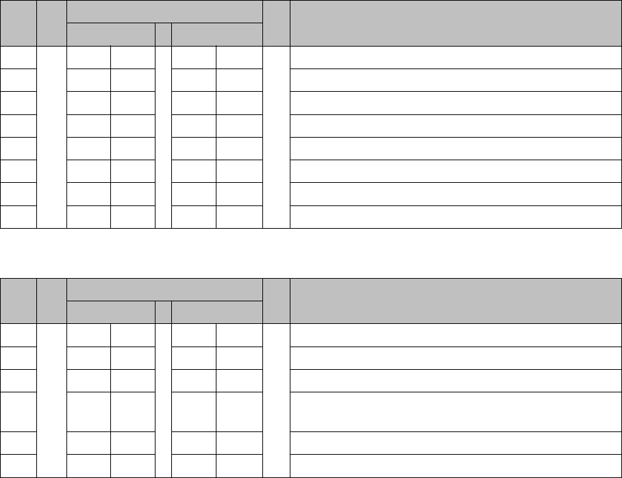
Version state 01 and 02: DIP switch settings (8 pin)
* Not all gantries may be available, depending on the machine type.
Version state 03 and higher: DIP switch settings (6 pin)
* Not all gantries may be available, depending on the machine type.
See also
5.6.1 Vision LED driver VLT 33 [03039244-xx] [ ➙ 331]
S Setting for gantry* Comments
1 2
1OFFOFFBootstrap
2OFFOFFReset
3OFFOFFGantry ID 0
4OFFONGantry ID 1
5OFFOFFTest
6OFFOFFCAN terminator
7ON ON CAN speed: ON: 1 Mbit/s, OFF: 500 KB/s
8 xx xx OFF: FC camera (type 25), ON: IC camera (type 33)
S Setting for gantry* Comments
1 2
1OFFOFFReset
2OFFOFFGantry ID 0
3OFFONGantry ID 1
4 x x x x LED: This switch is delivered with a fixed presetting.
Do not change this setting!
5OFFOFFCAN terminator
6 xx xx OFF: FC camera (type 25), ON: IC camera (type 33)
Settings
Other Settings 4.9.4 DIP Switch for Camera Types 25 and 33
298 Service Manual SIPLACE SX1/SX2/DX1/DX2 FS02
Description of the Circuit Boards
5.1.1 CAN switch [03083844-xx] Electrics and Control
Service Manual SIPLACE SX1/SX2/DX1/DX2 FS02 299
5
5 Description of the Circuit Boards
Description of the Circuit Boards
Numerous circuit boards are installed on placement machines, which are equipped with LEDs, 7-seg-
ment displays, switches and jumpers.
In this manual the statuses and functions of the visual displays on the circuit boards for diagnostic pur-
poses are listed. The description of the switches and jumper settings, for example, helps to replace cir-
cuit boards, configure the new circuit board correctly or verify the configuration of a previously installed
circuit board.
5.1
5.1 Electrics and Control
Electrics and Control
5.1.1
5.1.1 CAN switch [03083844-xx]
CAN switch [03083844-xx]
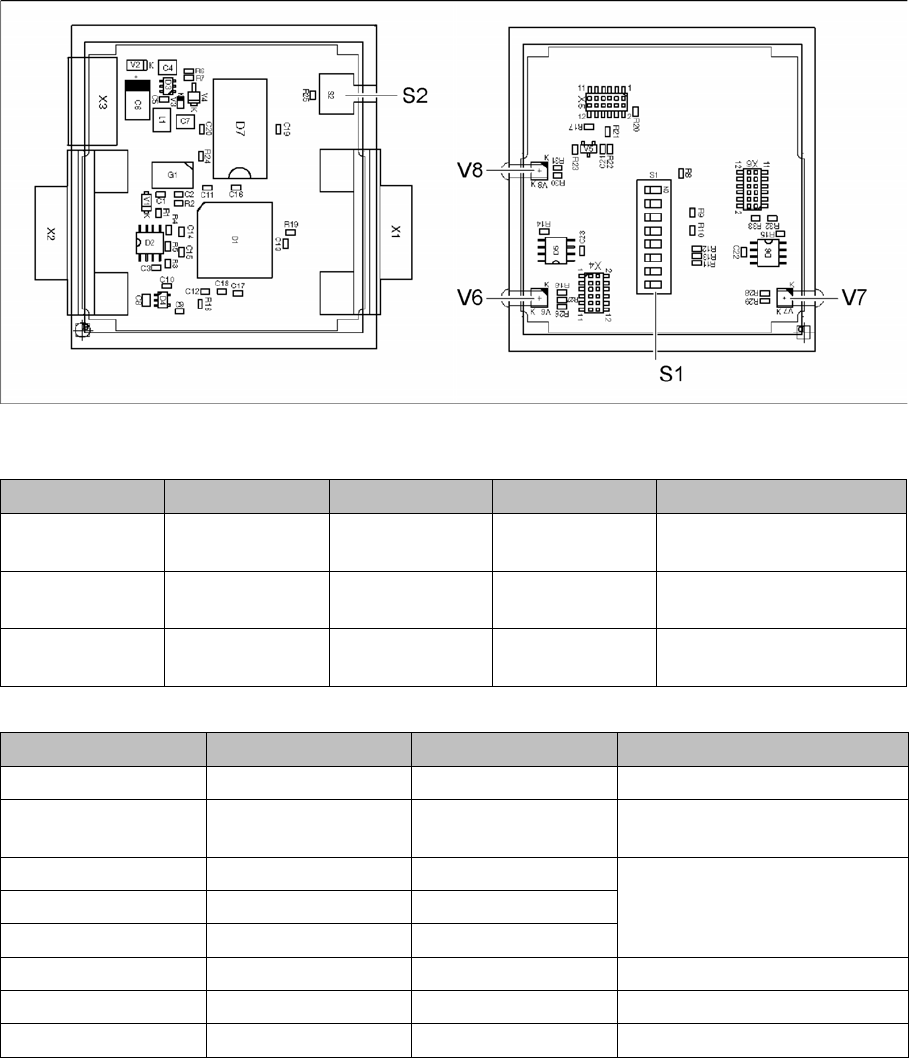
03083844-02
LED [03083844-02]
Dip switch S1 [03083844-02]
LED Color Status Signal name Description
V6 GN/RD ON P20.12/
RST001_N
1 Mbit transmission rate:
GN OK, RD: error
V7 GN/RD ON P20.4/ALE 500 kbit transmission rate:
GN OK, RD: error
V8 GN/RD ON P9./CC16IO Transmission rate:
GN 1Mbit, RD 500kbit
Switch Status Signal name Description
S1.1 OFF P5.0/AN0 ON: DIP test
S1.2 ON/OFF P5.1/AN1 ON: 500 kbit
OFF: 1 Mbit
S1.3 ON/OFF P5.2/AN2 See table Error Frame Limits
S1.4 ON/OFF P5.3/AN3
S1.5 ON/OFF P5.4/AN4
S1.6 OFF P5.5/AN5 OFF: no test, ON: testing
S1.7 ON CAN1RB 120ohms, CAN1
S1.8 ON CAN2RB 120ohms, CAN2