00196497-07_SM_SXDX12_en.pdf - 第310页
Description of the Circuit Boards Electrics and Control 5.1.5 Inrush Current Limitation Board Tran sformer (A1) [03066830-xx] 310 Service Manual SIPLACE SX1/SX2/DX1/DX2 FS02 5.1.5 5 . 1 . 5 I n r u s h C u r r e n t L im…
Description of the Circuit Boards
5.1.4 Fuse Connection Board Electrics and Control
Service Manual SIPLACE SX1/SX2/DX1/DX2 FS02 309
5.1.4
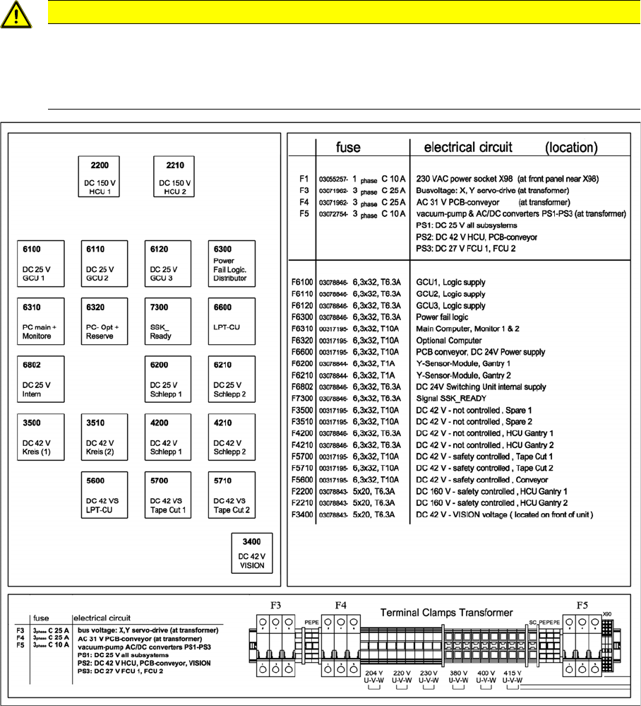
5.1.4 Fuse Connection Board
Fuse Connection Board
A fuse kit [03078912-xx] for the power supply is included with the delivery of the machine in a separate
package or may be in the power supply.
CAUTION
Observe the detailed circuit diagrams!
For more detailed information, refer to the circuit diagrams folder.
► SIPLACE SX1/SX2/DX1/DX2 detailed circuit diagrams [00196475-xx] (German and Eng-
lish)
Description of the Circuit Boards
Electrics and Control 5.1.5 Inrush Current Limitation Board Transformer (A1) [03066830-xx]
310 Service Manual SIPLACE SX1/SX2/DX1/DX2 FS02
5.1.5
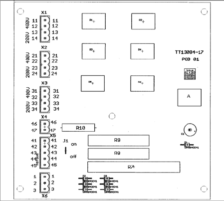
5.1.5 Inrush Current Limitation Board Transformer (A1) [03066830-xx]
Inrush Current Limitation Board Transformer (A1) [03066830-xx]
03066830-01
Jumper J1:
HF/X series: jumper to ON
SX4: jumper to OFF
SX1/SX2: The jumper is not queried here. The
jumper setting is therefore irrelevant.
Description of the Circuit Boards
5.2.1 Head Interface C700B [03055072-xx] Gantry
Service Manual SIPLACE SX1/SX2/DX1/DX2 FS02 311
5.2
5.2 Gantry
Gantry
5.2.1
5.2.1 Head Interface C700B [03055072-xx]
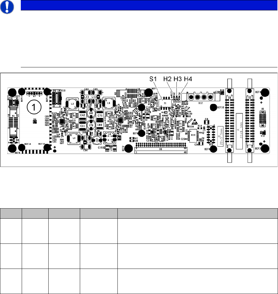
Head Interface C700B [03055072-xx]
The "Module Head Interface C700B" [03055072-xx] contains the "PCB Head Interface C700B"
[03055071-xx] and the "Module Powercube" [03055514-xx] amongst others.
03055071-05
1. Assembly position of the Module / Powercube [03055514-xx]
LED [03055071-05]
NOTICE
C&P20 P
The following additional conditions must be fulfilled for operating a C&P20 P:
► The head interface must have function state [03055072-05] at least (with head interface
board [03055071-07]).
► The MODULE / Powercube must have at least function state [03055514-02].
► You find a complete list of the prerequisites in section Replacing the C&P20 P Head.
LED Color Status Signal name Description
H2 RD ON POWERFAI
L_BASE_3V
POWERFAIL signal enabled by power supply
PF - lights up if the PowerFail signal is triggered by the
power supply
H3 RD ON EMERGEN
CY_STOP_
3V
Cover open, emergency STOP enabled
E_STOP - Emergency-Stop – shines when cover open and
emergency STOP activated
H4 GN ON P3V3 3.3 V voltage OK
FPGA - monitors the microcontroller on the basic adapter
board (should always be green)