00196497-07_SM_SXDX12_en.pdf - 第313页
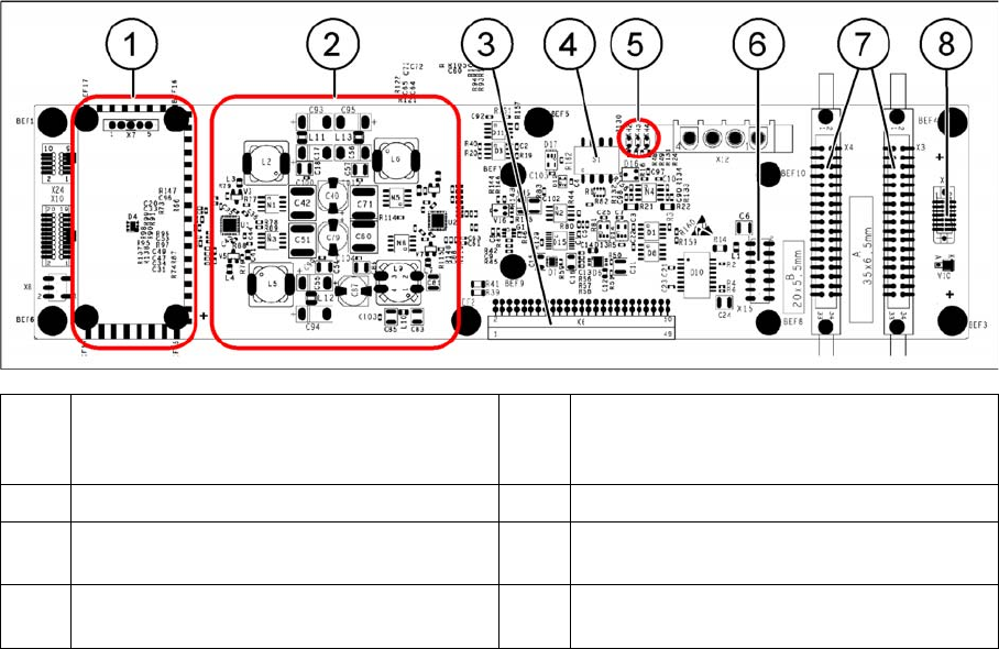
Description of the Circuit Boards 5.2.1 Head Interface C700B [03055072-xx] Gantry Service Manual SIPLACE SX1/SX2/DX1/DX2 FS02 313 Head interface C700 (1) Powercube X7 24V (input 40V) (2) DC/DC converter +15 V, - 15 V, +5…
Description of the Circuit Boards
Gantry 5.2.1 Head Interface C700B [03055072-xx]
312 Service Manual SIPLACE SX1/SX2/DX1/DX2 FS02
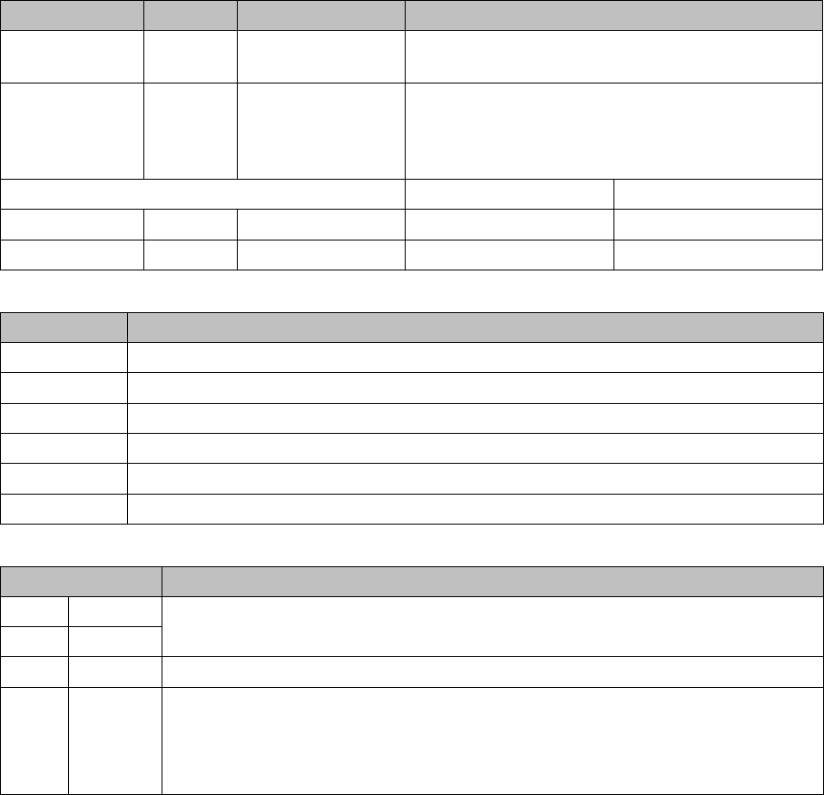
DIP switch block S1 [03055071-05]
Terminals (selection)
Switch S1
Switch Status Signal name Description
S1.1 OFF DCDC_OFF Standard mode, ON: RESET only possible when
not all the voltages are present
S1.2 OFF FAN Standard mode: automatic operation, when the
hood is open, the fans of the X/Y motors are
switched off
ON: fans are always switched on
Gantry 1 Gantry 2
S1.3 ON/OFF GANTRY_ID1 OFF ON
S1.4 ON/OFF GANTRY_ID0 OFF OFF
Terminal Description
X3, X4 Gantry interface
X5 Vision board (CAN_H/L)
X6 Base adapter board
X10 SPS option
X14 Incremental encoder (new)
X15 Incremental encoder (old)
Switch Description
1P0 Gantry coding:
gantry 1: P1=OFF, P2=OFF – gantry 2: P1=OFF, P2=ON
2P1
3FANFan: OFF (standard) automatic mode – ON: fan always on
4 DC/DC DC/DC converter:
OFF: standard
ON: Reset - Reset is only possible, if not all the voltages are present (PowerFail
LEDs on the basic adapter board).
Description of the Circuit Boards
5.2.1 Head Interface C700B [03055072-xx] Gantry
Service Manual SIPLACE SX1/SX2/DX1/DX2 FS02 313
Head interface C700
(1) Powercube X7 24V (input 40V) (2) DC/DC converter +15 V, -15 V, +5 V,
+3.3 V, +1.5 V (input 24 V from power
cube)
(3) X6 – connection for basic adapter board (4) DIP switch S1
(5) LEDs H2 to H4 (6) X15 – Connection for incremental encoder
(old)
(7) X3, X4 – connection for gantry interface (8) X5 – connection for vision board (CAN_H/
L)
Description of the Circuit Boards
Gantry 5.2.2 Vision board spread spectrum HCU1 [03067289-xx]
314 Service Manual SIPLACE SX1/SX2/DX1/DX2 FS02
5.2.2
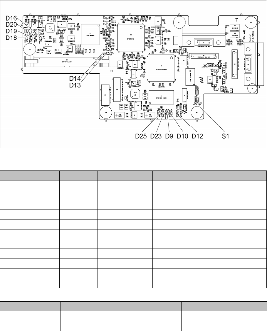
5.2.2 Vision board spread spectrum HCU1 [03067289-xx]
Vision board spread spectrum HCU1 [03067289-xx]
03067289-02
LED [03067289-02]
Dip switch S1 [03067289-02]
All switches must be set to OFF. If required, the CAN controller can be reset with the reset switch.
LED Color Status Signal name Description
D9 GN ON LED_XC_OK RUN
D10 RD ON LED_XC_ERR ERROR
D12 RD ON XC_RESET RESET
D13 GN ON IO/LVDS51P CO camera active
D14 GN ON IO/LVDS51N PCB camera active
D16 GN ON P12VCAM_I +12VDC for camera
D18 GN ON P5VCAM +5VDC for camera
D19 GN ON P2.5VCAM + 2.5 VDC for camera
D20 GN ON P3.3VCAM + 3.3VDC for camera
D23 GN ON P5V +5VDC
D25 GN ON P15V +15VDC
Switch Status Signal name Description
S1.1 OFF HW_RESET ON: RESET CAN controller
S1.2 OFF CAN_ID Not used