00196497-07_SM_SXDX12_en.pdf - 第317页
Description of the Circuit Boards 5.2.5 Base adapter Gantry Service Manual SIPLACE SX1/SX2/DX1/DX2 FS02 317 5.2.5 5 . 2 . 5 B a s e a d a p t e r Base adapter 5.2.5.1 5 . 2 . 5 . 1 B a s e a d a p t e r C & P [ 0 3 0…
Description of the Circuit Boards
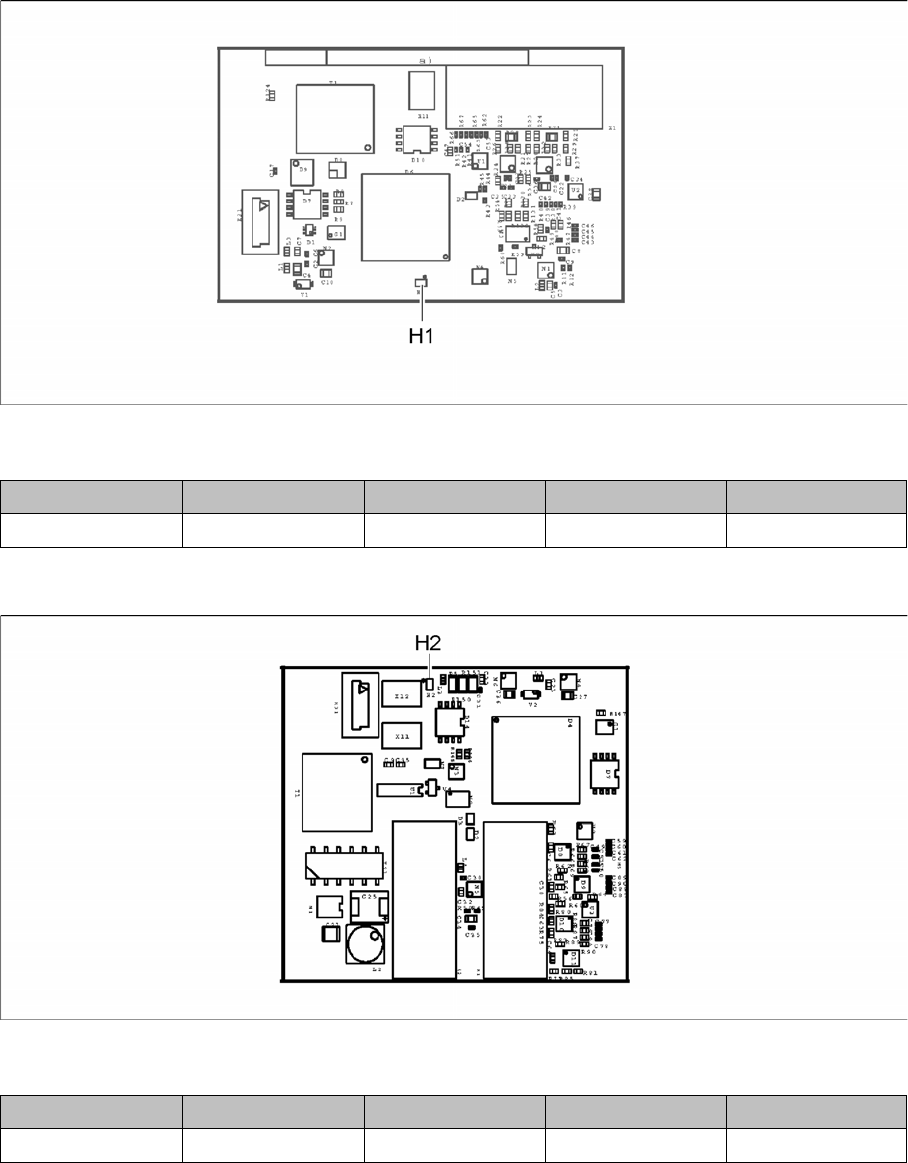
Gantry 5.2.3 Sensor module X axis [03068500-xx]
316 Service Manual SIPLACE SX1/SX2/DX1/DX2 FS02
5.2.3
5.2.3 Sensor module X axis [03068500-xx]
Sensor module X axis [03068500-xx]
03068500-03
LED [03068500-03]
5.2.4
5.2.4 Sensor module Y axis [03064608-xx]
Sensor module Y axis [03064608-xx]
03064608-01
LED [03064608-01]
LED Color Status Signal name Description
H1 GN ON FPGA_RUN_N FPGA OK
LED Color Status Signal name Description
H2 GN ON FPGA_RUN_N FPGA OK
Description of the Circuit Boards
5.2.5 Base adapter Gantry
Service Manual SIPLACE SX1/SX2/DX1/DX2 FS02 317
5.2.5
5.2.5 Base adapter
Base adapter
5.2.5.1
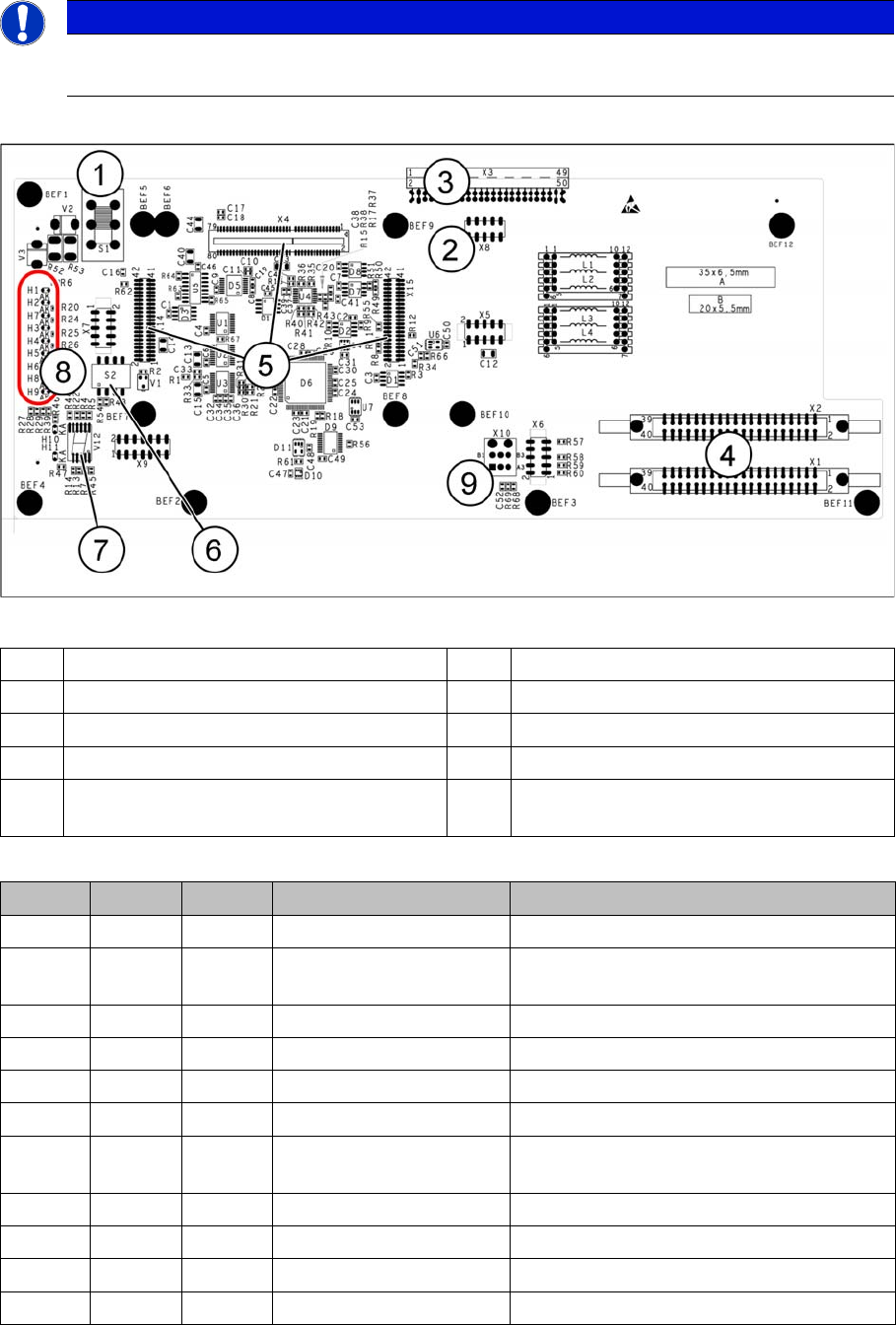
5.2.5.1 Base adapter C&P [03055516-xx]
Base adapter C&P [03055516-xx]
This board is used for the C&P20x and CPP heads on SX1/SX2/DX1/DX2 machines.
03055516-07
LED [03055516-03]
NOTICE
C&P20 P
If you are converting to a C&P20 P, the base adapter must have at least function state -06.
1 Switch S1 (see below) 2 X4 – for checking the voltages
3 Connection to the head interface C700 4 X1 and X2 – to the head
5 X4, X14 and X15 – for the HCU 6 DIP switch S2
7 7 segment display 8 LEDs H1-H11
9 X10 – Connection for vacuum pressure
sensor (if present)
LED Color Status Signal name Description
H1 GN ON CO_SENSOR CO sensor active
H2 GN ON - The programming plug for the HCU is con-
nected
H3 RD ON FPGA_TEST_6 1.5V power supply error
H4 RD ON FPGA_TEST_2 3.3V power supply error
H5 RD ON FPGA_TEST_4 5V power supply error
H6 RD ON FPGA_TEST_1 15V power supply error
H7 RD ON FPGA_TEST_3 DP power supply error, temp. without func-
tion
H8 RD ON FPGA_TEST_5 24V power supply error
H9 RD ON POWERFAIL_LOCAL PowerFail on circuit board
H10 RD ON HCU_LED_ERROR HCU error
H11 GN ON HCU_LED_OK HCU running without errors

Description of the Circuit Boards
Gantry 5.2.5 Base adapter
318 Service Manual SIPLACE SX1/SX2/DX1/DX2 FS02
7-segment display V12 [03055516-03]
Switch S1 []03055516-03
Dip switch S2 [03055516-03]
Display Status Description
Decimal point Flashes HCU1 OK
Switch Status Function
S1 40 V Intermediate circuit voltage for Z axis/C&P20 head
150 V Intermediate circuit voltage for Z axis/CPP head
Switch Status Signal name Description
S2.1 OFF HCU_CM_FPGA_IO_0 Gantry ID not used
S2.2 OFF HCU_CM_FPGA_IO_1 Gantry ID not used
S2.3 OFF RESET_HCU1 RESET HCU
S2.4 OFF COM_BOOT_HCU BOOTSTRAP function for HCU