00196497-07_SM_SXDX12_en.pdf - 第322页
Description of the Circuit Boards Conveyor 5.3.1 TSP400 [03057341-xx] 322 Service Manual SIPLACE SX1/SX2/DX1/DX2 FS02 Button S1, S2 [03057341-02] Dip switch S3 [03057341-02] Jumper [03057341-02] Jumper Buttons Status Sig…
Description of the Circuit Boards
5.3.1 TSP400 [03057341-xx] Conveyor
Service Manual SIPLACE SX1/SX2/DX1/DX2 FS02 321
5.3
5.3 Conveyor
Conveyor
5.3.1
5.3.1 TSP400 [03057341-xx]
TSP400 [03057341-xx]
03057341-02
LED [03057341-02]
Switches and buttons
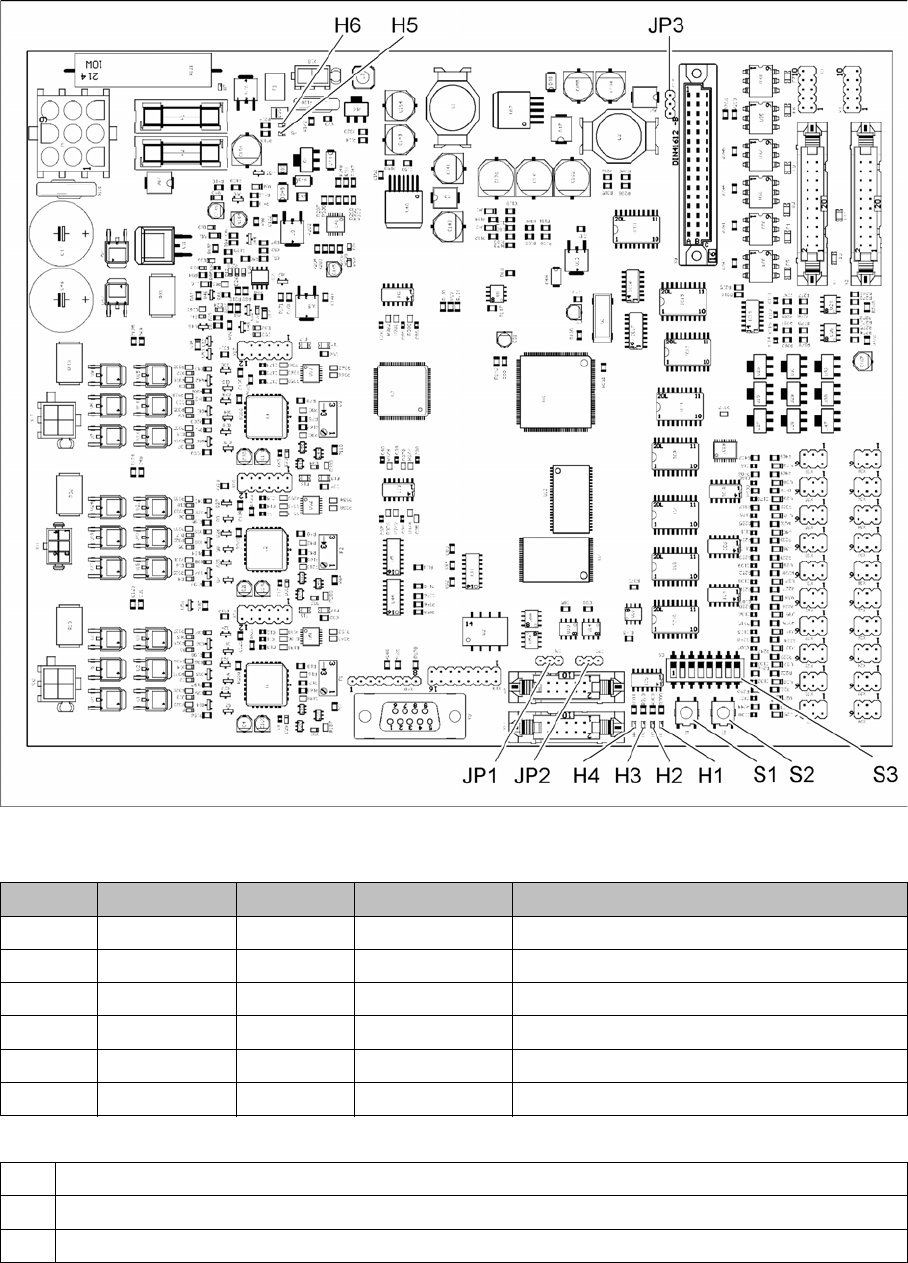
LED Color Status Signal name Description
H1 RD ON LED_FAIL Error
H2 GN ON LED_RUN Running (operation)
H3 YE ON LED_CAN1 CAN bus activity of machine
H4 YE ON LED_CAN2 CAN bus activity of conveyor lane 1/2
H5 GN ON P40V +40VDC voltage supply is present
H6 GN ON +24 V +24VDC voltage supply is present
S1 Reset XC167 (used for eSW development only)
S2 Reset XC167 (used for eSW development only)
S3 Configuration for single and dual conveyor
Description of the Circuit Boards
Conveyor 5.3.1 TSP400 [03057341-xx]
322 Service Manual SIPLACE SX1/SX2/DX1/DX2 FS02
Button S1, S2 [03057341-02]
Dip switch S3 [03057341-02]
Jumper [03057341-02]
Jumper
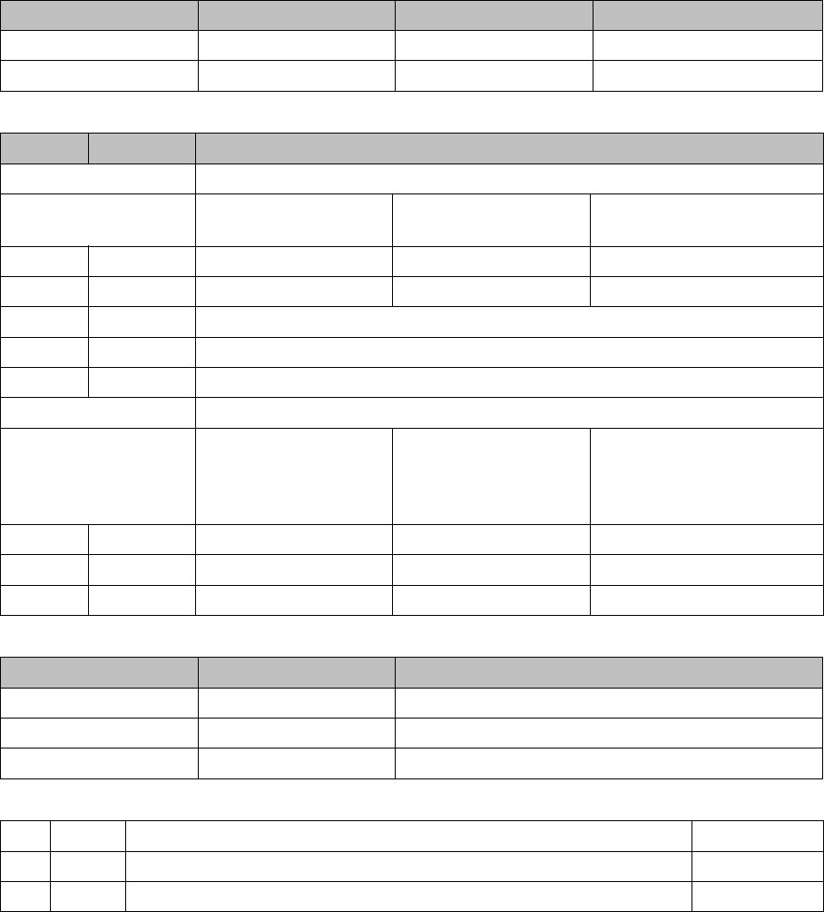
Buttons Status Signal name Description
S1 When pressed /MR RESET
S2 When pressed /BSL BOOT
Switch Status Function
PCB conveyor configuration
Single conveyor Dual lane conveyor
lane 1
Dual lane conveyor
lane 2
S3.1 ON/OFF OFF OFF ON
S3.2 ON/OFF OFF ON OFF
S3.3 OFF -
S3.7 OFF -
S3.8 OFF Flash memory internal, ON: flash memory external
Stopper configuration
Electromagnetic stop-
pers installed, stoppers
feedback sensors in-
stalled
Electromagnetic stop-
pers installed, stopper
feedback sensors not
installed
Electromagnetic stoppers
not installed
S3.4 ON/OFF OFF ON OFF
S3.5 ON/OFF OFF OFF ON
S3.6 ON/OFF OFF OFF OFF
Jumper Status Description
JP1 2 - 3 CAN bus terminating resistor, machine: OFF
JP2 1 – 2 CAN bus terminating resistor, lane 1 – 2: ON
JP3 1 - 2 Voltage supply stopper: internal
JP1 2-3 Terminating resistor for CAN bus of machine: Off
JP2 1-2 Terminating resistor for CAN bus of conveyor lane 1 or 2: On
JP3 1-2 Trigger signal, stopper: Internal
Description of the Circuit Boards
5.3.1 TSP400 [03057341-xx] Conveyor
Service Manual SIPLACE SX1/SX2/DX1/DX2 FS02 323
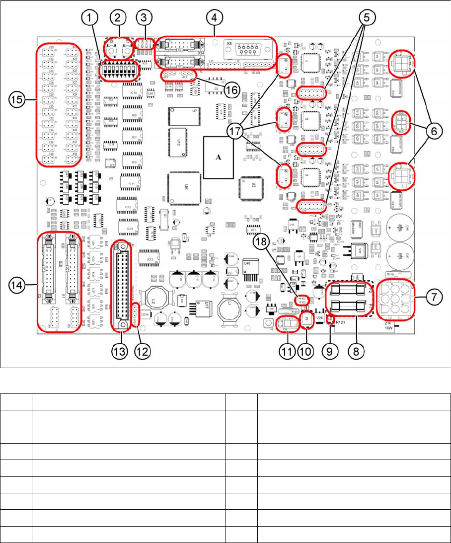
Overview
03057341-01
(1) DIP switch S3 (2) Button S1 and S2
(3) LEDs H1 to H4 (4) Connectors X7, X8, X14, X19 and X40
(5) Connectors X15 to X17 (6) Connectors X10 to X12
(7) Plug X5 (8) Fuses F1 and F2
(9) LED H7 (10) Fuse F3
(11) Plug X18 (12) Jumper JP3
(13) Plug X9 (14) Connectors X1 and X2
(15) Connectors X20 to X39 (16) Jumpers JP1 and JP2
(17) Potentiometers P1 to P3 (18) LED H5 and H6