00196497-07_SM_SXDX12_en.pdf - 第323页
Description of the Circuit Boards 5.3.1 TSP400 [03057341-xx] Conveyor Service Manual SIPLACE SX1/SX2/DX1/DX2 FS02 323 Overview 03057341-01 (1) DI P switch S3 (2) Button S1 and S2 (3) LEDs H1 to H4 (4) Connectors X7, X8, …

Description of the Circuit Boards
Conveyor 5.3.1 TSP400 [03057341-xx]
322 Service Manual SIPLACE SX1/SX2/DX1/DX2 FS02
Button S1, S2 [03057341-02]
Dip switch S3 [03057341-02]
Jumper [03057341-02]
Jumper
Buttons Status Signal name Description
S1 When pressed /MR RESET
S2 When pressed /BSL BOOT
Switch Status Function
PCB conveyor configuration
Single conveyor Dual lane conveyor
lane 1
Dual lane conveyor
lane 2
S3.1 ON/OFF OFF OFF ON
S3.2 ON/OFF OFF ON OFF
S3.3 OFF -
S3.7 OFF -
S3.8 OFF Flash memory internal, ON: flash memory external
Stopper configuration
Electromagnetic stop-
pers installed, stoppers
feedback sensors in-
stalled
Electromagnetic stop-
pers installed, stopper
feedback sensors not
installed
Electromagnetic stoppers
not installed
S3.4 ON/OFF OFF ON OFF
S3.5 ON/OFF OFF OFF ON
S3.6 ON/OFF OFF OFF OFF
Jumper Status Description
JP1 2 - 3 CAN bus terminating resistor, machine: OFF
JP2 1 – 2 CAN bus terminating resistor, lane 1 – 2: ON
JP3 1 - 2 Voltage supply stopper: internal
JP1 2-3 Terminating resistor for CAN bus of machine: Off
JP2 1-2 Terminating resistor for CAN bus of conveyor lane 1 or 2: On
JP3 1-2 Trigger signal, stopper: Internal
Description of the Circuit Boards
5.3.1 TSP400 [03057341-xx] Conveyor
Service Manual SIPLACE SX1/SX2/DX1/DX2 FS02 323
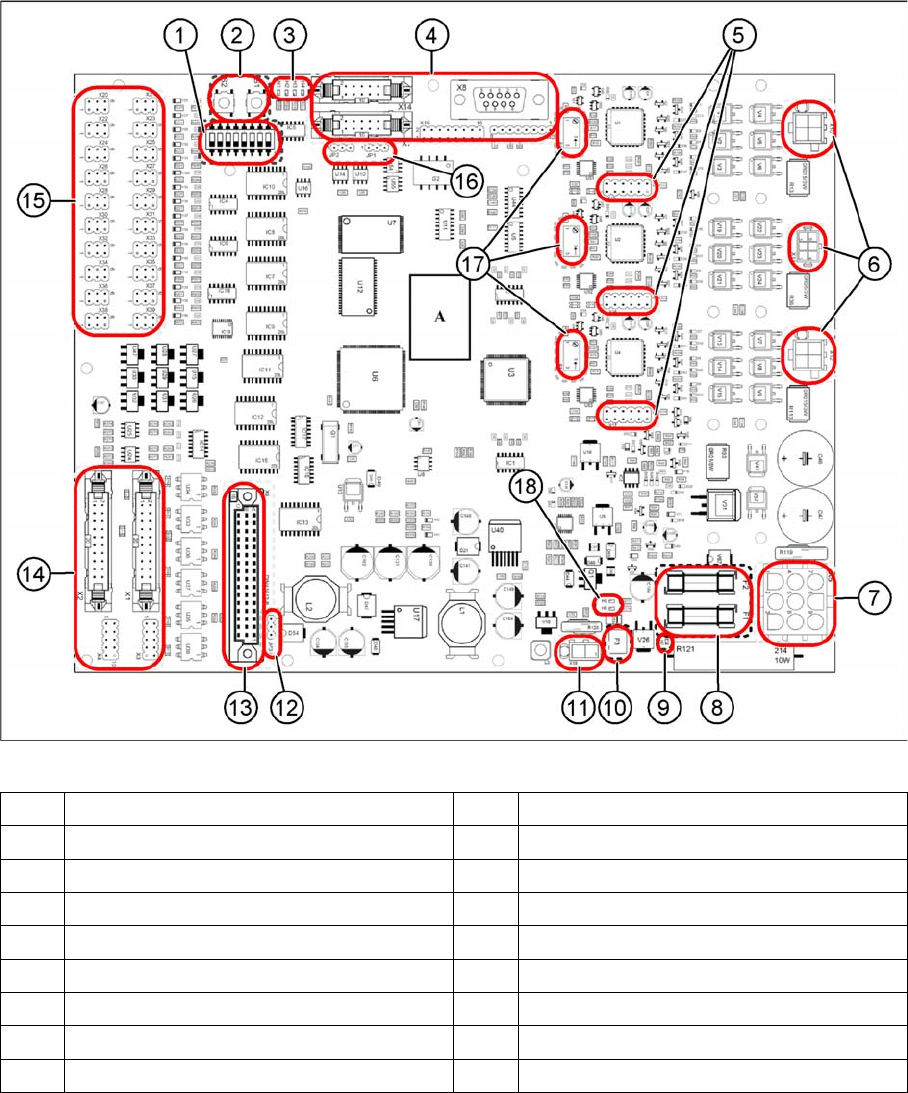
Overview
03057341-01
(1) DIP switch S3 (2) Button S1 and S2
(3) LEDs H1 to H4 (4) Connectors X7, X8, X14, X19 and X40
(5) Connectors X15 to X17 (6) Connectors X10 to X12
(7) Plug X5 (8) Fuses F1 and F2
(9) LED H7 (10) Fuse F3
(11) Plug X18 (12) Jumper JP3
(13) Plug X9 (14) Connectors X1 and X2
(15) Connectors X20 to X39 (16) Jumpers JP1 and JP2
(17) Potentiometers P1 to P3 (18) LED H5 and H6

Description of the Circuit Boards
Conveyor 5.3.1 TSP400 [03057341-xx]
324 Service Manual SIPLACE SX1/SX2/DX1/DX2 FS02
Connector
Fuses
Potentiometer
X1 Siemens interface, upstream station X21 Board sensor placement area
X2 Siemens interface, downstream station X22 Spare
X3 SMEMA interface, upstream station X23 Board sensor output area
X4 SMEMA interface, downstream station X24 Sensor conveyor side width adjustment
unit 1
X5 Power supply X25 Sensor conveyor side wall, width adjust-
ment unit 2
X26 Sensor cylinder width adjustment unit 1
X7 CAN bus to machine controller X27 Sensor cylinder width adjustment unit 2
X8 V24 interface for troubleshooting (debug) X28 Spare
X9 Interface to board TSP400E (optional) X29 Stopper Long Board Option coding (togeth-
er with X37)
X10 Motor for conveyor belt X30 Spare
X11 Width adjustment motor X31 Spare
X12 Motor, lifting table X32 Pneumatic valve width adjustment unit 1
X33 Pneumatic valve width adjustment unit 2
X14 CAN bus to conveyor lane X34 Spare
X15 Track signals, conveyor motor X35 Stopper, input area
X16 Track signals, width adjustment motor X36 Stopper, placement area
X17 Track signals, lifting table motor X37 Stopper Long Board Option (together with
X29)
X18 Brake, lifting table X38 Stopper, output area
X19 Programming interface for development X39 Spare
X20 Board sensor input area X40 Programming interface for development
F1 [03079942-xx] Miniature fuse
5x20 / T 2A / ceramic
T2A Fuse protection
24V
(sensors, control system supply)
F2 [03078843-xx] miniature fuse
5x20 / T 6.3A / ceramic
T6.3A Fuse protection
40V
(supply, drives)
F3 Self-healing SMD fuse Polyswitch set for 24 V (supply, lifting table brake), not
replaceable
P1 Setting the zero point of the control loop for the lifting table/conveyor belt/width adjustment motor
(needs to be performed only once
P2 by the manufacturer and is then sealed with locking varnish). The potentiometer will be dis-
pensed with in future
P3 and replaced with an eSW teach function.