00196497-07_SM_SXDX12_en.pdf - 第327页
Description of the Circuit Boards 5.4.2 Connecting assy FCU [03059783-xx] COT inser t Service Manual SIPLACE SX1/SX2/DX1/DX2 FS02 327 Test mode for reject bin switc hed off – S2.1 ON [03059783- 04 LE D] Test mode for rej…
Description of the Circuit Boards
COT insert 5.4.1 Insert control [03079305-xx]
326 Service Manual SIPLACE SX1/SX2/DX1/DX2 FS02
5.4
5.4 COT insert
COT insert
5.4.1
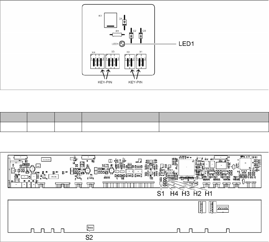
5.4.1 Insert control [03079305-xx]
Insert control [03079305-xx]
[03078869-02], part of [03079305-xx]
LED [03079305-02]
5.4.2
5.4.2 Connecting assy FCU [03059783-xx]
Connecting assy FCU [03059783-xx]
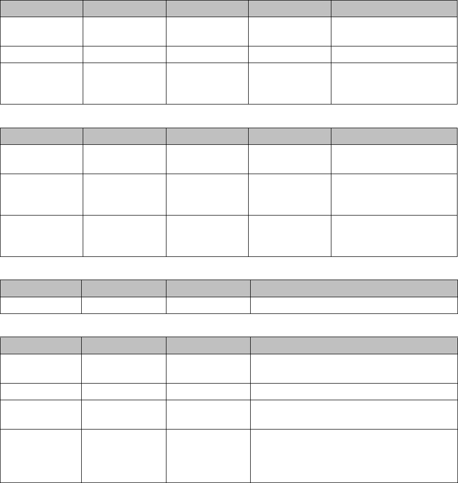
03059783-04
LED Color Status Signal name Description
LED1 GN ON S_DOCKED CO trolley docked
Description of the Circuit Boards
5.4.2 Connecting assy FCU [03059783-xx] COT insert
Service Manual SIPLACE SX1/SX2/DX1/DX2 FS02 327
Test mode for reject bin switched off – S2.1 ON [03059783-04 LED]
Test mode for reject box switched on – S2.1 OFF [03059783-04 LED]
Button S1 [03059783-04]
DIP switch S2 [03059783-04]
LED Color Status Signal name Description
H1, H2, H3, H4 GN Sequential shift
light
LED1, 2, 3, 4 FCU OK
H1, H2, H3, H4 GN ON LED1, 2, 3, 4 eSW application missing
H1, H2, H3, H4 GN Flashing LED1, 2, 3, 4 FCU error, reboot place-
ment machine or replace
FCU
LED Color Status Signal name Description
H1 or H2 GN Flashes LED1 or 2 No sensor connected for
reject box 1 or 2
H1 or H2 GN OFF LED1 or 2 Sensor for reject boxes 1 or
2 connected, but no reject
box inserted
H1 or H2 GN ON LED1 or 2 Sensor for reject boxes 1 or
2 connected and reject
boxes inserted
Buttons Status Function Description
S1 OFF RESET When pressed
Switch Status Signal name Description
S2.1 ON/OFF FCU_ENV3 ON: test mode for reject box switched off
OFF: test mode for reject box switched on
S2.2 ON FCU_ENV2 60-fold FCU
S2.3 ON/OFF FCU_ENV1 ON: without insert control, with virtual button
OFF: with insert control, without virtual button
S2.4 ON/OFF FCU_ENV0 ON: with tape cutter and with nozzle changer
functionality
OFF: without tape cutter and without nozzle
changer functionality
Description of the Circuit Boards
COT insert 5.4.3 CAN bus terminator for CO table [03046863-xx]
328 Service Manual SIPLACE SX1/SX2/DX1/DX2 FS02
5.4.3
5.4.3 CAN bus terminator for CO table [03046863-xx]
CAN bus terminator for CO table [03046863-xx]
The "CAN bus terminal changeover table" ensures that the CAN bus still works even when a WPC is
fitted. During undocking, a CAN terminating resistor is switched, which maintains the CAN bus function
and communication.
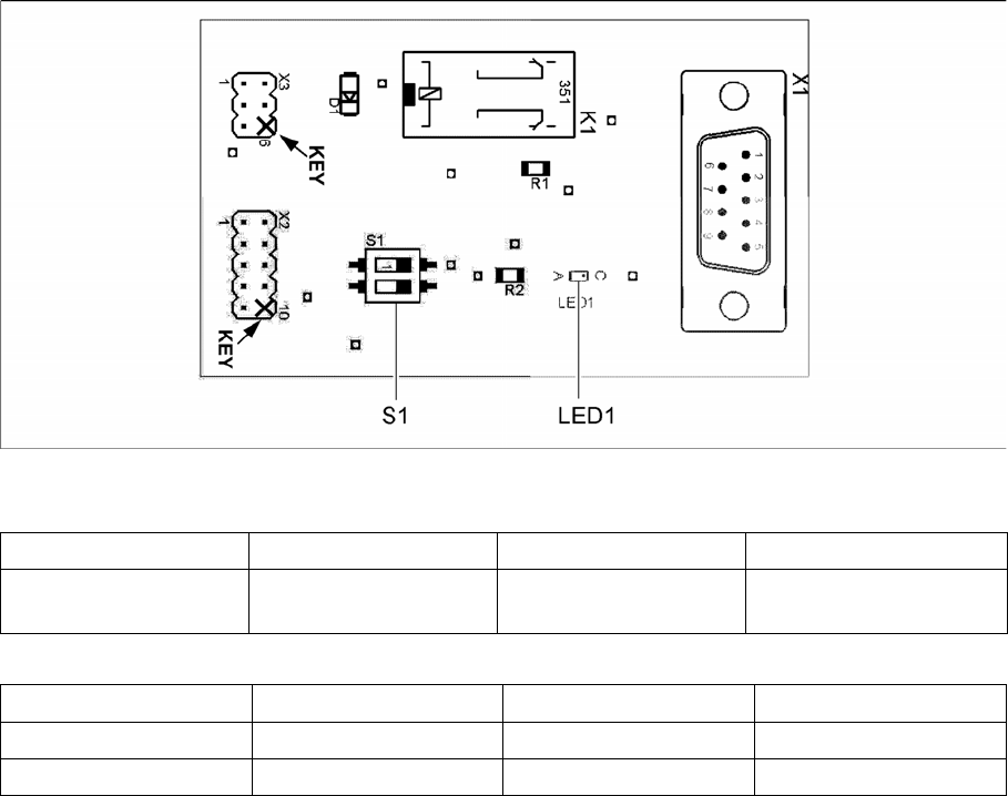
03046863-01
LED [03046863-01]
Switch [03046863-01]
LED Color Status Description
LED1 GN ON 24 VDC on connector
X3:4
Switch Signal name Location 1 (gantry 1) Location 2 (gantry 2)
S1.1 ADR_0 ON ON
S1.2 ADR_1 ON OFF