00196497-07_SM_SXDX12_en.pdf - 第37页
Service Work Conveyor 3.1.3 Flap Cover Stopper Basic Machine Service Manual SIPLACE SX1/SX2/DX1/DX2 FS02 37 3.1.3 3 . 1 . 3 F la p C o v e r S t o p p e r Flap Cover Stopper Parts, Equipment and Tools ▪ Stop left, cpl. […
Service Work Conveyor
Basic Machine 3.1.2 Guide Rollers on the Covers
36 Service Manual SIPLACE SX1/SX2/DX1/DX2 FS02
3.1.2
3.1.2 Guide Rollers on the Covers
Guide Rollers on the Covers
Parts, Equipment and Tools
▪ Per machine:
– 4x roller assembly - pack of 20 [03078561-xx]
– 4x DIN915-M8x16 - pack of 10 [00304354-xx]
or
4x DIN EN ISO4026-M8x16-A2-21H - pack of 10 [03025582-xx]
▪ Open-ended wrench, size 10
▪ Allen key
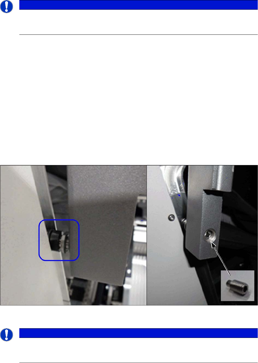
Procedure
► To make the work easier, proceed as follows:
SX1/SX2: Open the two gantry changer doors and move the covers out of the guidance.
X-Series (S), SX4/DX4: dismantle the bottom stopper.
► Loosen the screwed fixture on the roller (fork wrench size 10). Unscrew as far as required.
► From the inside, screw on a setscrew as lock and tighten it.
Check
► Check whether the cover can be easily moved along the whole area. Adjust the cover if necessary
(see "4.2.1 Setting the Machine Covers" [ ➙ 249]).
NOTICE
Example
The following sections are described using the example of an SX1/SX2 machine. The proce-
dure is the same for other machines. Any relevant differences will be mentioned explicitly.
NOTICE
Covering
Between the roller and the guidance there must be at least 75% coverage along the entire
length of the guide rails.

Service Work Conveyor
3.1.3 Flap Cover Stopper Basic Machine
Service Manual SIPLACE SX1/SX2/DX1/DX2 FS02 37
3.1.3
3.1.3 Flap Cover Stopper
Flap Cover Stopper
Parts, Equipment and Tools
▪ Stop left, cpl. [03113746-xx]
Stop right, cpl. [03113750-xx]
(repace: [03086295-xx] and [03072728-xx])
3.1.4
3.1.4 Exchanging the Gantry Changer Doors
Exchanging the Gantry Changer Doors
Parts, Equipment and Tools
Select the appropriate version:
Both versions are not compatible. The following parts are required for conversion:
Version 1:
▪ SX1/SX2:
Door left cpl. [03074871-xx] / Door right cpl. [03074867-xx]
– 2x Guide rail vertical, door [03074863-xx]
– 6x DIN EN ISO 7380-M3 x 6-A2-70 [03045194-xx]
▪ DX1/DX2:
Door left cpl. [03082494-xx] / Door right cpl. [03082911-xx]
– 2x Guide rail vertical, door [03074863-xx]
– 6x DIN EN ISO 7380-M3 x 6-A2-70 [03045194-xx]
Version 2:
▪ SX1/SX2, DX1/DX2:
Door left cpl. [03091950-xx] / Door right cpl. SX12/ DX12 [03089768-xx]
– 2x Guide rail vertical, door [03082793-xx]
– 6x DIN EN ISO 7380-M3 x 6-A2-70 [03045194-xx]
NOTICE
New flap cover stopper on SIPLACE SX1/2, DX1/2
Possible problems:
➢ Breakage of the rollers on the protective covers
➢ Improper closing of the flap covers
➢ Badly adjusted cover guidances or stoppers
► Also read the Technical Information "New stopper on folding covers for SIPLACE SX1 /
DX1" [DE: TI2014-04D05] [EN: TI2014-04E05].
► Read section "4.2.1 Setting the Machine Covers" [ ➙ 249].
NOTICE
Various versions
There are two gantry changer door versions. Installation and removal is described based on
version 1. For version 2, proceed in the same manner. Any differences will be explicitly indicat-
ed.
Door left Door right
Version 1 (keyboard at the monitor) 03074871-xx 03074867-xx
Version 2 (keyboard at the gantry changer door) 03091950-xx 03089768-xx
NOTICE
Observing the Technical Information
► Observe the Technical Information "New stopper on folding covers for SIPLACE SX1 /
DX1" [DE: TI2014-04D05] [EN: TI2014-04E05].
Service Work Conveyor
Basic Machine 3.1.4 Exchanging the Gantry Changer Doors
38 Service Manual SIPLACE SX1/SX2/DX1/DX2 FS02
Removal
Installation
► Follow the removal instructions in reverse order for installation. Also observe the following instruc-
tions:
NOTICE
Washers etc.
► Note all positions of washers, springs etc. to ensure their correct assignment later on.
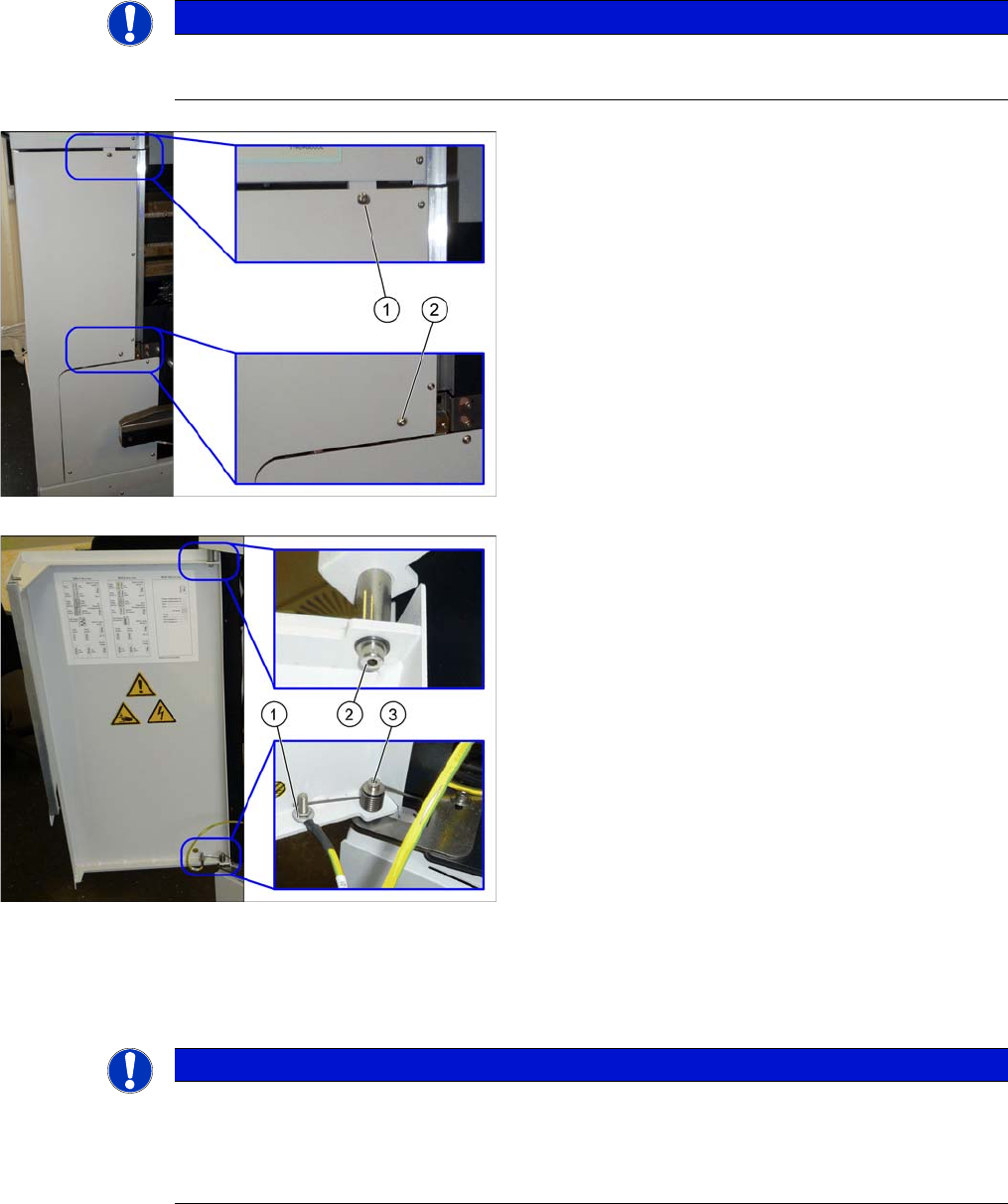
► Open the flap cover.
► Lift off the keyboard.
► Remove the two fastening screws (1) and (2) on the
gantry changer doors.
► Remove the fastening screw (1) of the grounding ca-
ble.
► Remove the lower fastening screw (3) of the gantry
changer door and lift off the spring.
► Remove the upper fastening screw (2) of the gantry
changer door.
Here, you find two washers: a smaller one on the side
of the screw head, a bigger one on the side of the cyl-
inder.
► Lift the gantry changer door out of the lower cylinder.
NOTICE
Installation instructions
► Make sure to insert the spring in the correct orientation (see figure above).
► Check and, if necessary, correct the setting of the cover guidance, the bottom stopper, and
the cover rollers (see "4.2.1 Setting the Machine Covers" [ ➙ 249]).