00196497-07_SM_SXDX12_en.pdf - 第45页
Service Work Conveyor 3.2.7 Replacing the Inrush Current Limitation Board Ser vo (A1) [03058951-xx] Electrical System Service Manual SIPLACE SX1/SX2/DX1/DX2 FS02 45 3.2.7 3 . 2 . 7 R e p la c in g t h e I n r u s h C u r…
Service Work Conveyor
Electrical System 3.2.6 Replacing the Inrush Current Limitation Board Transformer (A1) [03066830-
44 Service Manual SIPLACE SX1/SX2/DX1/DX2 FS02
3.2.6
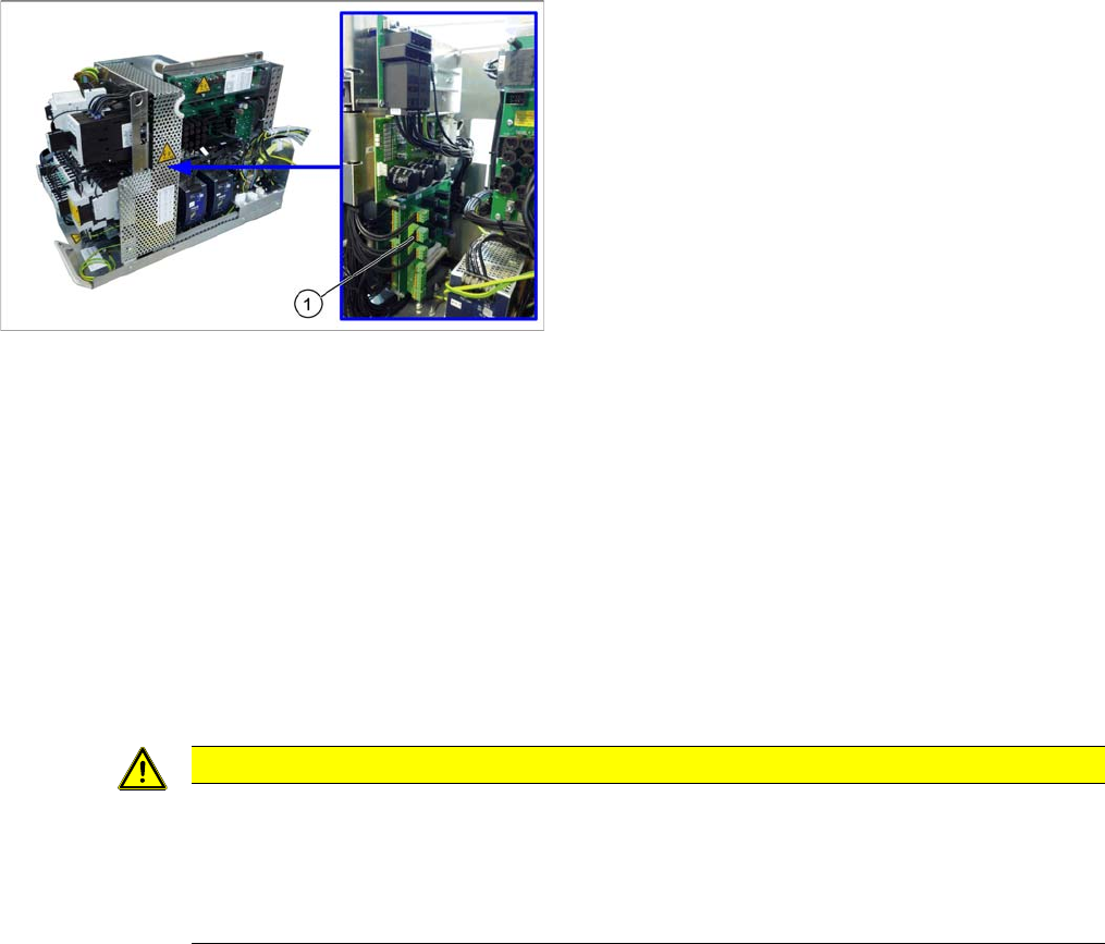
3.2.6 Replacing the Inrush Current Limitation Board Transformer (A1) [03066830-xx]
Replacing the Inrush Current Limitation Board Transformer (A1) [03066830-xx]
Parts, equipment and tools
▪ Inrush current limitation board transformer [03066830-xx]
Overview
Removal
► Switch off the machine, disconnect it from the power supply and secure it to prevent unauthorized
reactivation. Observe the instructions in section "1.2 Preparatory Work..." [ ➙ 13].
► Loosen the screws fastening the mesh cover and then remove the cover.
► Unplug all connections to board A1. You may want to mark their positions, to make clear assignment
easier later on.
► Loosen the screws fastening board A1 and then remove the board.
Installation
► Follow the removal instructions in reverse order for installation. Also observe the following instruc-
tions:
1. Two boards are fitted above one another here.
Front: inrush current limitation board for transformer
(A1)
Behind: inrush current limitation board for servo (A2)
CAUTION
Installation instructions
► Check the correct input voltage. (See "3.2.3 Checking the Input Voltage at the Inrush Cur-
rent Limitation Board (A1)" [ ➙ 41])
► Check the correct jumper setting. (See "5.1.5 Inrush Current Limitation Board Transformer
(A1) [03066830-xx]" [ ➙ 310])
Service Work Conveyor
3.2.7 Replacing the Inrush Current Limitation Board Servo (A1) [03058951-xx] Electrical System
Service Manual SIPLACE SX1/SX2/DX1/DX2 FS02 45
3.2.7
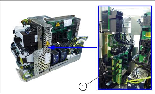
3.2.7 Replacing the Inrush Current Limitation Board Servo (A1) [03058951-xx]
Replacing the Inrush Current Limitation Board Servo (A1) [03058951-xx]
Parts, Equipment and Tools
▪ Inrush current limitation board servo [03058951-xx]
Overview
Removal
► Switch off the machine, disconnect it from the power supply and secure it to prevent unauthorized
reactivation. Observe the instructions in section "1.2 Preparatory Work..." [ ➙ 13].
► Loosen the screws fastening the mesh cover and then remove the cover.
► Unplug all connections to board A1. You may want to mark their positions, to make clear assignment
easier later on.
► Loosen the screws fastening board A1 and then remove the board.
► Unplug all connections to board A2. You may want to mark their positions, to make clear assignment
easier later on.
► Loosen the screws fastening board A2 and then remove the board.
Installation
► Follow the removal instructions in reverse order for installation.
1. Two boards are fitted above one another here.
Front: inrush current limitation board for transformer
(A1)
Behind: inrush current limitation board for servo (A2)
Service Work Conveyor
Electrical System 3.2.8 Replacing the Rectifier Board (A7) [03069283-xx]
46 Service Manual SIPLACE SX1/SX2/DX1/DX2 FS02
3.2.8
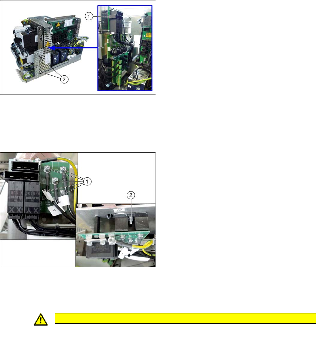
3.2.8 Replacing the Rectifier Board (A7) [03069283-xx]
Replacing the Rectifier Board (A7) [03069283-xx]
Parts, equipment and tools
▪ Rectifier board [03069283-xx]
▪ Heat-conductive paste
Overview
Removal
► Switch off the machine, disconnect it from the power supply and secure it to prevent unauthorized
reactivation. Observe the instructions in section "1.2 Preparatory Work..." [ ➙ 13].
► Loosen the screws fastening the mesh cover and then remove the cover.
Installation
► Follow the removal instructions in reverse order for installation. Also observe the following instruc-
tions:
1. Rectifier board (A7)
2. Fastening screws of the mesh cover
► Unplug all connections to board A7. You may want to
mark their positions, to make clear assignment easier
later on.
► Loosen the fastening screws on board A7. Now the
board is only connected to the rectifiers.
► The rectifiers are screwed to the cooling surface.
Loosen the fastening screws of the rectifiers (1)
and (2).
► Lift off the board and the rectifiers.
CAUTION
Installation instructions
► Clean the surfaces of the cooling element before reinstallation.
► Apply the heat-conductive paste in a thin layer onto the rectifiers. Take the old board as an
example, if necessary.