00196497-07_SM_SXDX12_en.pdf - 第57页
Service Work Conveyor 3.2.14 Replacing the Motor Circuit Breaker PKE32/XTU-3 2 [03098183-xx] Electrical System Service Manual SIPLACE SX1/SX2/DX1/DX2 FS02 57 ► Unplug the electrical c onnections to the protective m otor …
Service Work Conveyor
Electrical System 3.2.14 Replacing the Motor Circuit Breaker PKE32/XTU-32 [03098183-xx]
56 Service Manual SIPLACE SX1/SX2/DX1/DX2 FS02
Removal
► Switch off the machine, disconnect it from the power supply and secure it to prevent unauthorized
reactivation. Observe the instructions in section "1.2 Preparatory Work..." [ ➙ 13].
Checking the Power Supply for Absence of Voltage
► Before you start working, check the power supply for absence of voltage and observe the waiting
times!
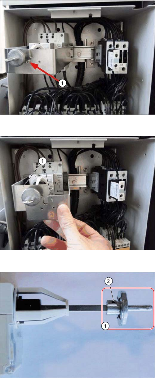
Shaft support, fitted (example of SX1)
► Remove the fastening screw (1) on the shaft support.
Shaft support, remove (example of SX1)
► Remove the two shaft support plates (1) from the DIN
rail. The plates are locked in place on the DIN rail with
gray clamping blocks.
Switch bracket
► Loosen the grub screw (2) at the switch bracket (1)
and pull the switch bracket off.
Service Work Conveyor
3.2.14 Replacing the Motor Circuit Breaker PKE32/XTU-32 [03098183-xx] Electrical System
Service Manual SIPLACE SX1/SX2/DX1/DX2 FS02 57
► Unplug the electrical connections to the protective motor switch. Mark their positions, to make clear
assignment easier later on.
► Mark the position of the protective motor switch on the DIN rail.
► Lift the protective motor switch off the DIN rail.
Installation
► Remove the shunt release from the old protective motor switch and install it on the new one. Also
read section "3.2.15 Replacing the Shunt Release A-PKZ0 24VDC [03102397-xx]" [ ➙ 61].
► Fit the new protective motor switch together with the shunt release on the DIN rail. Make sure to po-
sition and align it correctly (observe the marking).
► Reestablish all electrical connections.
The clamping screws are fastened with a torque. The valid torque values are printed on the packag-
ing of the protective motor switch:
Flexible cable 1.5 - 4 mm² → 1.7 Nm
Dismantling the axis support
► Remove the screw (1), and remove the position indi-
cator on the axis.
► Remove the screw (2).
► Slightly turn the axis support to the left until you see
the snap tabs (3).
► Pull the axis support out towards the front.
NOTICE!
The snap tabs easily break.
NOTICE
Orientation of the protective motor switch
In older machines, the protective motor switch is installed at an angle of 180°. In this case the
connectors 1 to T3 are located on top.
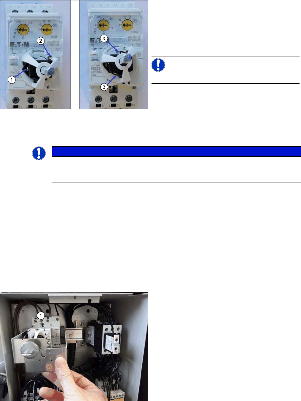
Shaft support, fitted (example of SX1)
► Fit the two shaft support plates (1) on the DIN rail.
Have the gray clamping blocks engage with the DIN
rail.
Service Work Conveyor
Electrical System 3.2.14 Replacing the Motor Circuit Breaker PKE32/XTU-32 [03098183-xx]
58 Service Manual SIPLACE SX1/SX2/DX1/DX2 FS02
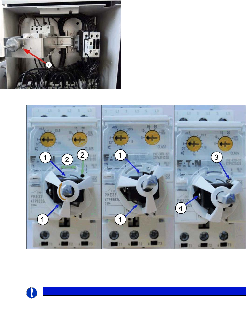
Fitting the axis support
► Gently insert the axis support and attach the switching axis (do not fix it yet).
Make sure that the two snap tabs of the axis support (1) can lock in place with the protective motor
switch by slightly rotating the axis support (green arrow). The hole in the base of the axis support (2)
is now above a hole in the PKE switch.
► Fix the axis support on the protective motor switch with the supplied (3) screw. Tighten the screw
with a torque of 0.5 to 1 Nm. The screw is self-drilling.
► Adjust the position indicator on the axis. In the switched-off position, the arrow points to the left if the
setting screws of the PKZ are on top. Fix the position indicator with the screw (4). Tighten the screw
with a torque of 0.5 to 1 Nm.
Shaft support, fitted (example of SX1)
► Secure the two shaft support plates with the fastening
screw (1).
NOTICE
The snap tabs easily break.
Proceed with caution as the snap tabs easily break.