00196497-07_SM_SXDX12_en.pdf - 第62页
Service Work Conveyor Electrical System 3.2.16 Replacing the Cover Switch [0 3055263-xx] 62 Service Manual SIPLACE SX1/SX2/DX1/DX2 FS02 3.2.16 3 . 2 . 1 6 R e p la c in g t h e C o v e r S w it c h [ 0 3 0 5 5 2 6 3 - x …
Service Work Conveyor
3.2.15 Replacing the Shunt Release A-PKZ0 24VDC [03102397-xx] Electrical System
Service Manual SIPLACE SX1/SX2/DX1/DX2 FS02 61
3.2.15
3.2.15 Replacing the Shunt Release A-PKZ0 24VDC [03102397-xx]
Replacing the Shunt Release A-PKZ0 24VDC [03102397-xx]
Parts, Equipment and Tools
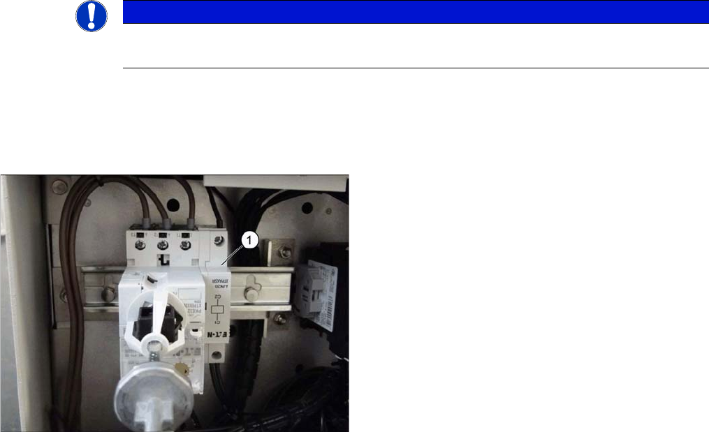
▪ Shunt release A-PKZ0 24VDC [03102397-xx]
Overview
Removal
► Switch off the machine, disconnect it from the power supply and secure it to prevent unauthorized
reactivation. Observe the instructions in section "1.2 Preparatory Work..." [ ➙ 13].
Checking the Power Supply for Absence of Voltage
► Before you start working, check the power supply for absence of voltage and observe the waiting
times!
► Dismantle the motor protections switch (see "3.2.14 Replacing the Motor Circuit Breaker PKE32/
XTU-32 [03098183-xx]" [ ➙ 55]).
► Lift the shunt release off the protective motor switch.
Installation
► Installation is performed by following the above instructions in the reverse order.
NOTICE
Not for US network 3x208 V
The shunt release is not present in the 2x208 V US network.
The shunt release (1) is located on the side of the protec-
tive motor switch.
Service Work Conveyor
Electrical System 3.2.16 Replacing the Cover Switch [03055263-xx]
62 Service Manual SIPLACE SX1/SX2/DX1/DX2 FS02
3.2.16
3.2.16 Replacing the Cover Switch [03055263-xx]
Replacing the Cover Switch [03055263-xx]
Parts, Equipment and Tools
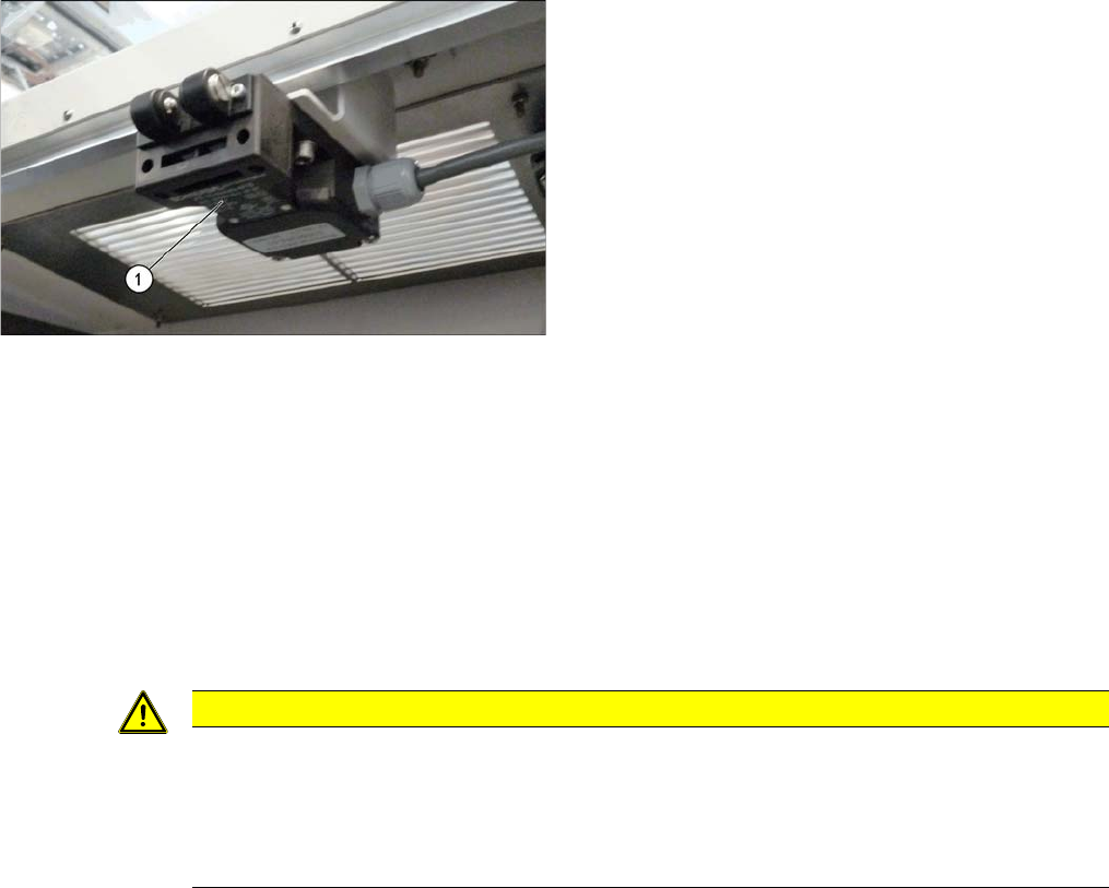
▪ Safety switch AZ 16-03zvrk-M16 3Oe [03055263-xx]
Overview
Removal
► Switch off the machine, disconnect it from the power supply and secure it to prevent unauthorized
reactivation. Observe the instructions in section "1.2 Preparatory Work..." [ ➙ 13].
► Unplug the connection cable from the cover switch.
► Remove the screws fastening the cover switch.
Installation
► Follow the removal instructions in reverse order for installation. Also observe the following instruc-
tions:
1. Cover switch
CAUTION
Installation instructions
► Make the adjustments for the cover switch (see "4.2.1.4 Setting the Cover Switch"
[ ➙ 251]).
► Switch the machine on and make sure that the cover switch activates the safety circuit,
when the protective covers are opened.
Service Work Conveyor
3.2.17 Replacing the Cover Fan [03094598-xx] Electrical System
Service Manual SIPLACE SX1/SX2/DX1/DX2 FS02 63
3.2.17
3.2.17 Replacing the Cover Fan [03094598-xx]
Replacing the Cover Fan [03094598-xx]
Parts, Equipment and Tools
▪ Cover fan 1 part [03094598-xx]
Overview
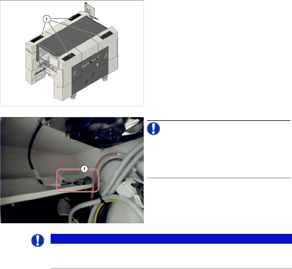
1. Cover fan (under the mesh covers)
NOTICE!
NTC resistors on machines from No. N001 upwards:
On machines from serial number N001 upwards, two
NTC resistors each (1) are connected upstream in series
on all four cover fans to limit the inrush current.
Inrush current limiter cover fan [03124362-xx]
NOTICE
NTC resistors on machines from No. N001 upwards
On machines from serial number N001 upwards, two NTC resistors each are connected up-
stream in series on all four cover fans to limit the inrush current.