00196497-07_SM_SXDX12_en.pdf - 第69页
Service Work Conveyor 3.3.1 Replacing the Video Multiplexer Splitter / VGA Splitter C able (Machine Nos.: Kxxx/ Lxxx/Mxxx only) Control Service Manual SIPLACE SX1/SX2/DX1/DX2 FS02 69 Installation ► Unpl ug all cables ( (…
Service Work Conveyor
Control 3.3.1 Replacing the Video Multiplexer Splitter / VGA Splitter Cable (Machine Nos.:
68 Service Manual SIPLACE SX1/SX2/DX1/DX2 FS02
3.3
3.3 Control
Control
See also
5 Description of the Circuit Boards [ ➙ 299]
3.3.1
3.3.1 Replacing the Video Multiplexer Splitter / VGA Splitter Cable (Machine Nos.: Kxxx/Lxxx/Mxxx only)
Replacing the Video Multiplexer Splitter / VGA Splitter Cable (Machine Nos.: Kxxx/
Lxxx/Mxxx only)
Parts, Equipment and Tools
The video multiplexer splitter [03057965-xx] is replaced by a new video splitter. In case of replacement,
you need the following spare part kit:
▪ Spare Part Kit VGA Splitter Cable [03082983-xx]
Contents:
– 1x splitter cable VGA 2 port [03076910-xx]
– 1x mini gender changer HD15 Bu - HD15 Bu [03082986-xx]
– 1x USB extension cable A-St - A-Bu 1.5 m [03074536-xx]
– 20x cable tie (B = 3.6 mm, L = 140 mm) TY 24M [00805141-xx]
You need the following tools for this:
▪ Allen key, size 2.5
▪ Diagonal cutters
Removal
NOTICE
For machine nos.: Kxxx, Lxxx und Mxxx only
From machine no.: N001 upwards, the cables are plugged in directly into the BoxPC.
► Switch off the machine, disconnect it from the power
supply and secure it to prevent unauthorized reacti-
vation. Observe the instructions in section "1.2 Pre-
paratory Work..." [ ➙ 13].
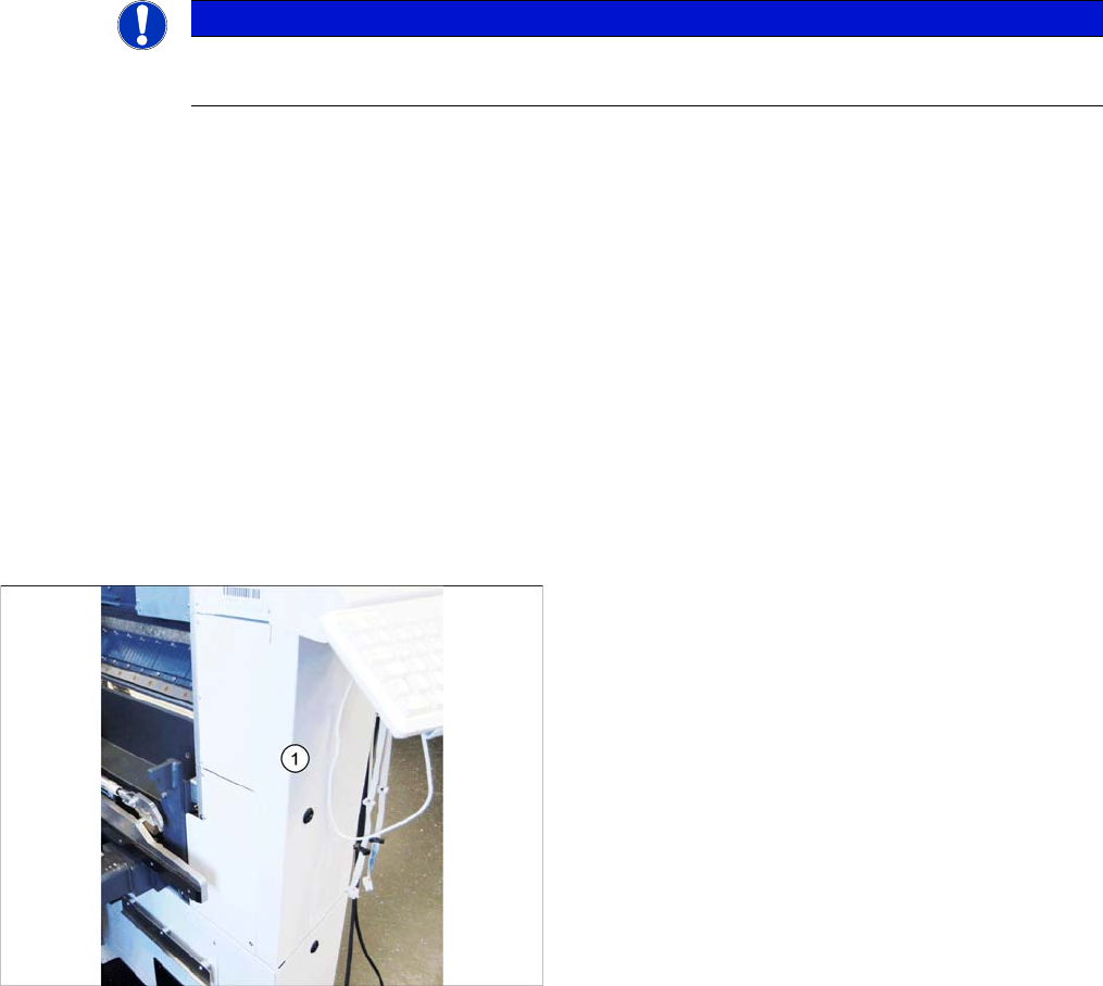
► At location 2, open the cover below the monitor.
Service Work Conveyor
3.3.1 Replacing the Video Multiplexer Splitter / VGA Splitter Cable (Machine Nos.: Kxxx/Lxxx/Mxxx only) Control
Service Manual SIPLACE SX1/SX2/DX1/DX2 FS02 69
Installation
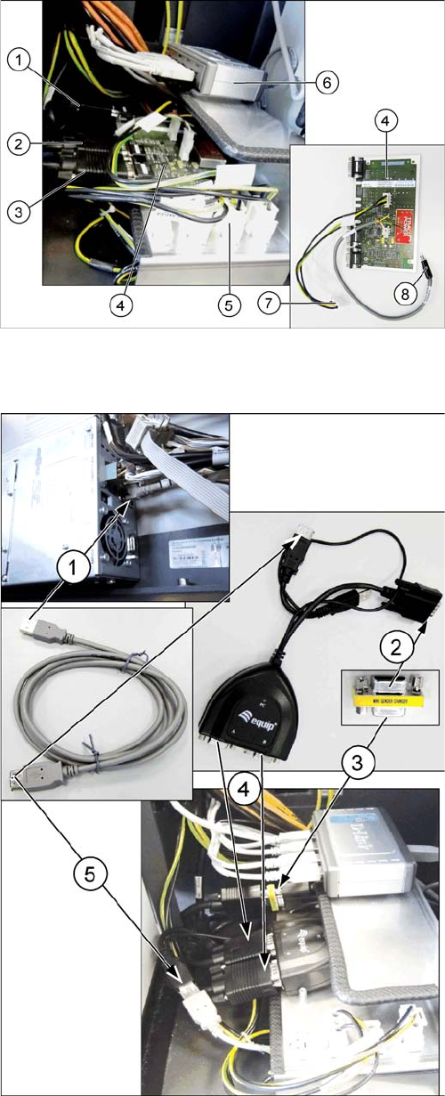
► Unplug all cables ((1), (2), (3)) from the defective vid-
eo multiplexer splitter (4).
► Remove the cable (7) from connection X2qv (5).
► Unplug the power supply cable (8) from the USB hub
(6). This cable will no longer be used. The line voltage
will be supplied via the existing USB cable from the
BoxPC in the future.
► Undo the four fastening screws (hexagon socket -
use Allen key) of the video multiplexer splitter and re-
move the splitter.
► Remove all cables which are not required.
► (1) Plug the USB extension cable into a free port of
the BoxPC and run the cable through the cable duct
to the installation position of the video splitter.
► (2) Connect the mini gender changer to the PC input
cable of the "Splitter cable VGA 2 port".
► (3) Then connect the cable "computer 1 – video mul-
tiplexer [03055251-xx]" to the other side of the mini
gender changer.
► (4) Connect the cables "monitor 1 – video multiplexer
[03055254-xx]" and "monitor 2 – video multiplexer
[03055253-xx]" to the inputs A and B of the "splitter
cable VGA 2 port".
► (5) Connect the USB cable to the USB connector of
the "splitter cable VGA 2 port". This is the power sup-
ply for "splitter cable VGA 2 port". When the machine
is switched on, the green LED indicates that voltage
is present.
► Follow the removal instructions in reverse order for
further installation.
Service Work Conveyor
Control 3.3.2 Replacing the I/O Control Unit [03116049-xx]
70 Service Manual SIPLACE SX1/SX2/DX1/DX2 FS02
3.3.2
3.3.2 Replacing the I/O Control Unit [03116049-xx]
Replacing the I/O Control Unit [03116049-xx]
Parts, Equipment and Tools
▪ I/O control unit II [03116049-xx]
(replaces: I/O control unit [03052315-xx])
Overview
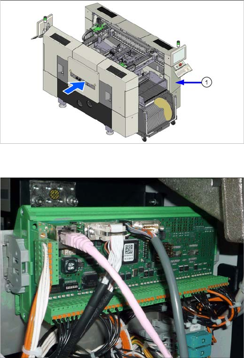
Installation position of I/O control unit
The I/O control unit is located under the cover (1), on the
right when viewed in the direction of transport.
I/O control unit II [03116049-xx]
I/O control unit
See the board description: "5.1.3 I/O control unit
[03116049-xx]" [ ➙ 303]