00196497-07_SM_SXDX12_en.pdf - 第81页
Service Work Conveyor 3.3.7 Replacing the RAM in the BoxPC Control Service Manual SIPLACE SX1/SX2/DX1/DX2 FS02 81 Removal ► Switch off the machine, disconnec t it from the po wer supply and secure it to prev ent unauth o…
Service Work Conveyor
Control 3.3.7 Replacing the RAM in the BoxPC
80 Service Manual SIPLACE SX1/SX2/DX1/DX2 FS02
3.3.7
3.3.7 Replacing the RAM in the BoxPC
Replacing the RAM in the BoxPC
Parts, Equipment and Tools
Overview
SXDX12V1V2
NOTICE
Memory extension
The Windows 7/8 operating system requires 2 GB of RAM.
Machine type PC type Operating sys-
tem
RAM module
X-Series S from no.:
H001
BoxPC 427D
[03114177Sxx]
Windows 8 4 GB DDR 1333Mhz PC3-10600
SO-DIMM
X-Series S up to no.:
Gxxx, SX4/DX4
BoxPC 827C
[03094732-xx]
Windows 7/8 At least 2 GB DDR3 1066 DIMM
SX1/SX2 up to no.:
Mxxx
BoxPC 627
[03055281-xx]
Windows 7/8 2 GB SDRAM DDR3 PC3-8500
[03099405-xx]
SX1/SX2 from no.:
N001
BoxPC ABP402-A
CPU1020E 2xPCI SSD-
80GB [03120423Sxx]
Windows 8 2x 2GB DDR3 SO-DIMM
BoxPC 627B/C
1. Memory extension
BoxPC ABP402-A iBase
1. Memory extension

Service Work Conveyor
3.3.7 Replacing the RAM in the BoxPC Control
Service Manual SIPLACE SX1/SX2/DX1/DX2 FS02 81
Removal
► Switch off the machine, disconnect it from the power supply and secure it to prevent unauthorized
reactivation. Observe the instructions in section "1.2 Preparatory Work..." [ ➙ 13].
► Dismantle and remove the BoxPC from the machine (see "3.3.3 Replacing the Control Computer
BoxPC" [ ➙ 72]).
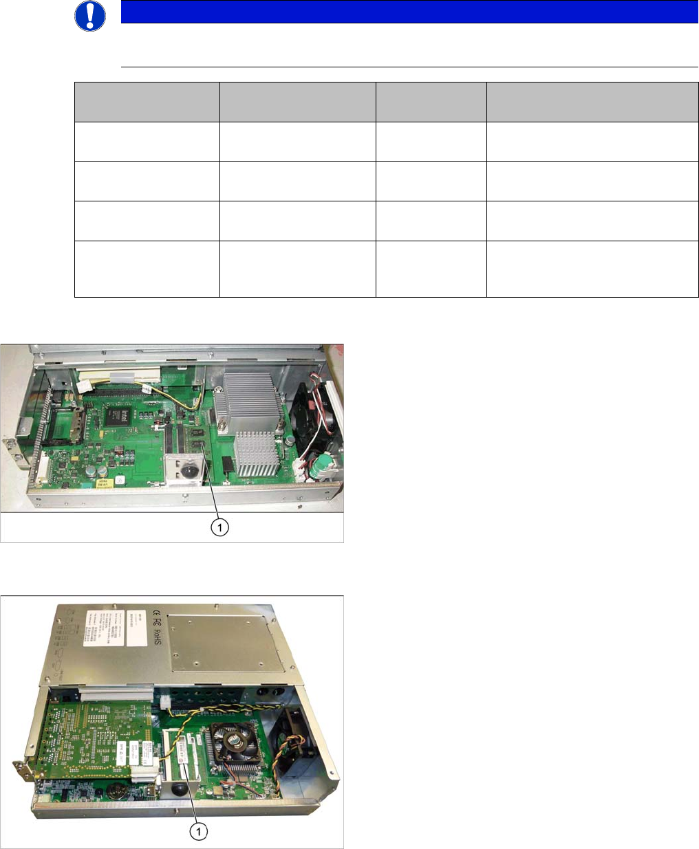
► Loosen the screws fastening the cover of the BoxPC and open the cover.
► Loosen the locks on both sides of the memory extension and remove the memory extension.
Installation
► Follow the removal instructions in reverse order for installation. Also observe the following instruc-
tions:
CAUTION
Installation instructions
► Make sure that you insert the memory extension the right way round. The new memory ex-
tension must audibly engage into its slot.
Service Work Conveyor
Control 3.3.8 Replacing the CAN Switch [03083844-xx]
82 Service Manual SIPLACE SX1/SX2/DX1/DX2 FS02
3.3.8
3.3.8 Replacing the CAN Switch [03083844-xx]
Replacing the CAN Switch [03083844-xx]
SXDX12V1V2
Parts, Equipment and Tools
▪ CAN switch [03083844-xx]
Overview
SXDX12V1 V2 – Installa tion Location
NOTICE
On machines up to no.: Mxxx only
The CAN switch is only used in machines up to serial nos.: Mxxx.
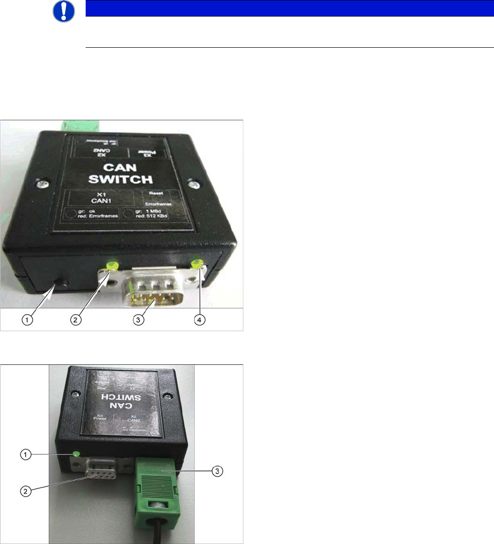
Description CAN 1
1. RESET – button
The button is used to reset the red LED on both sides,
CAN 1 and CAN 2.
2. LED green: setting 1Mbit
LED red: setting 500kBit
3. CAN bus cable connection CAN 1
4. LED green/red for CAN 1
Data transfer OK: green
Error frames received: red
Description CAN 2
1. LED green/red for CAN 2
Data transfer OK: green
Error frames received: red
2. CAN bus cable connection CAN 2
3. Voltage supply connection 24 V DC