00196497-07_SM_SXDX12_en.pdf - 第90页
Service Work Conveyor Gantries 3.4.5 Replacing the Gantry Interface Y [03065335 - xx] 90 Service Manual SIPLACE SX1/SX2/DX1/DX2 FS02 3.4.5 3 . 4 . 5 R e p la c in g t h e G a n t r y I n t e r f a c e Y [ 0 3 0 6 5 3 3 5…
Service Work Conveyor
3.4.4 Replacing the Gantry Interface X [03065078-xx] Gantries
Service Manual SIPLACE SX1/SX2/DX1/DX2 FS02 89
Installation
Adhesive Tape for Gantry Interface
► Follow the removal instructions in reverse order for installation. Also observe the following instruc-
tions:
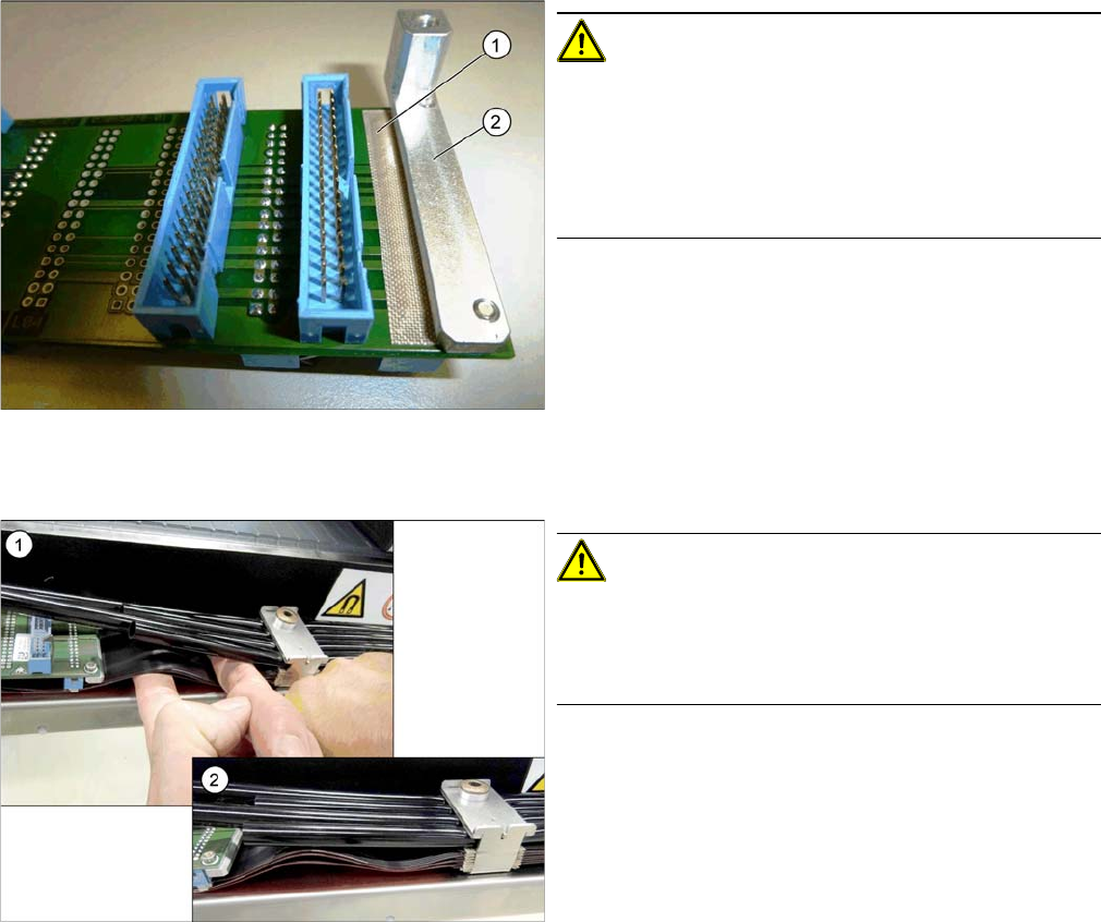
CAUTION!
During assembly, make sure that the connection rail con-
tacts are insulated with adhesive tape (1) in the direction
of the aluminum holder (2). Do not use conductive tape,
recommendation [03000372-xx] "PTFE glass fiber mate-
rial, self-adhesive, width 20mm" for insulating the con-
tacts.
CAUTION!
During installation, lay the flat ribbon cables of the X trail-
ing cable in a slight S shape to prevent the hoses from
pressing against the flat ribbon cables and the connec-
tors.
1. Bend the flat ribbon cable on the trailing interface into
shape
2. Flat ribbon cable on the trailing interface
Service Work Conveyor
Gantries 3.4.5 Replacing the Gantry Interface Y [03065335-xx]
90 Service Manual SIPLACE SX1/SX2/DX1/DX2 FS02
3.4.5
3.4.5 Replacing the Gantry InterfaceY [03065335-xx]
Replacing the Gantry Interface Y [03065335-xx]
Parts, equipment and tools
▪ Gantry interface Y [03065335-xx]
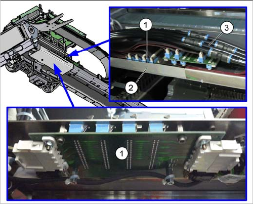
Overview
Removal
► Switch off the machine, disconnect it from the power supply and secure it to prevent unauthorized
reactivation. Observe the instructions in section "1.2 Preparatory Work..." [ ➙ 13].
► Unplug the pneumatic hoses which lead away from the gantry interface.
► Remove the covers above the board. Depending on the version the top cover is secured with press
studs or screws.
► Unplug the electrical connections on the top of the gantry interface. You may want to mark their po-
sitions, to make clear assignment easier later on.
► Loosen the two screws fastening the cover under the gantry interface.
► Unplug the electrical connections on the underside of the gantry interface. You may want to mark
their positions, to make clear assignment easier later on.
► Loosen the two screws fastening the gantry interface and remove the interface from the machine.
Installation
► Follow the removal instructions in reverse order for installation.
1. Gantry interface Y
2. Cover
3. Pneumatic hoses
Service Work Conveyor
3.4.6 Replacing the Sensor Interface [03060962-xx] Gantries
Service Manual SIPLACE SX1/SX2/DX1/DX2 FS02 91
3.4.6
3.4.6 Replacing the Sensor Interface [03060962-xx]
Replacing the Sensor Interface [03060962-xx]
Parts, Equipment and Tools
▪ Sensor interface [03060962-xx]
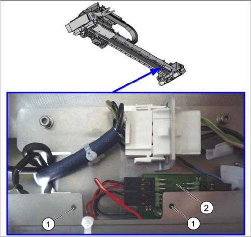
Overview
Removal
► Switch off the machine, disconnect it from the power supply and secure it to prevent unauthorized
reactivation. Observe the instructions in section "1.2 Preparatory Work..." [ ➙ 13].
► Loosen the two screws fastening the cover plate.
► Unplug the electrical connections to the sensor interface. You may want to mark their positions, to
make clear assignment easier later on.
► Loosen the screws fastening the sensor interface mount.
► Loosen the screws fastening the sensor interface to the mount and remove the sensor interface.
Installation
► Follow the removal instructions in reverse order for installation.
The sensor interface is on the underside of the gantry,
behind a cover.
1. Screws fastening the cover above the sensor inter-
face
(the cover has already been removed in the diagram).
2. Sensor interface