00196497-07_SM_SXDX12_en.pdf - 第96页
Service Work Conveyor Gantries 3.4.10 Replacing the Vision Hotlink Adapter [03050555-xx] 96 Service Manual SIPLACE SX1/SX2/DX1/DX2 FS02 Removal ► Switch off the machine, disconnec t it from the po wer supply and secure i…
Service Work Conveyor
3.4.10 Replacing the Vision Hotlink Adapter [03050555-xx] Gantries
Service Manual SIPLACE SX1/SX2/DX1/DX2 FS02 95
Installation
► Follow the removal instructions in reverse order for installation. Also observe the following instruc-
tions:
See also
5.2.2 Vision board spread spectrum HCU1 [03067289-xx] [ ➙ 314]
3.4.10
3.4.10 Replacing the Vision Hotlink Adapter [03050555-xx]
Replacing the Vision Hotlink Adapter [03050555-xx]
Parts, equipment and tools
▪ Vision hotlink adapter VHA [03050555-xx]
Overview
CAUTION
Installation instructions
► If there is no clamp for the PCB camera cable on the new board, take this off the old board
and fit it on the new one.
► Then perform a firmware update.
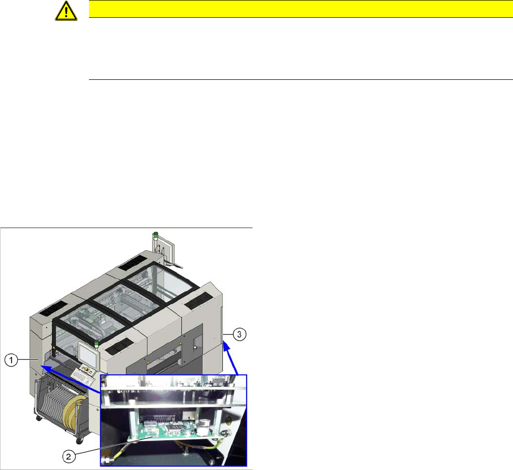
1. Sector 1
2. Vision hotlink adapter
3. Sector 3
The Vision hotlink adapter for gantry 1 is located in
sector 1.
The Vision hotlink adapter for gantry 2 (SX 2 only) is lo-
cated in sector 3.

Service Work Conveyor
Gantries 3.4.10 Replacing the Vision Hotlink Adapter [03050555-xx]
96 Service Manual SIPLACE SX1/SX2/DX1/DX2 FS02
Removal
► Switch off the machine, disconnect it from the power supply and secure it to prevent unauthorized
reactivation. Observe the instructions in section "1.2 Preparatory Work..." [ ➙ 13].
► Unplug the electrical connections to the trailing cable interface and the Vision hotlink adapter. Mark
their positions, to make clear assignment easier later on.
► Loosen the two screws fastening the mount. You can then push the mount backwards and lift it off
the fastening screws.
► Loosen the 4 screws fastening the Vision hotlink adapter and remove it from the mount.
Installation
► Follow the removal instructions in reverse order for installation.
See also
5.2.6 Vision hotlink adapter [03050555-xx] [ ➙ 320]
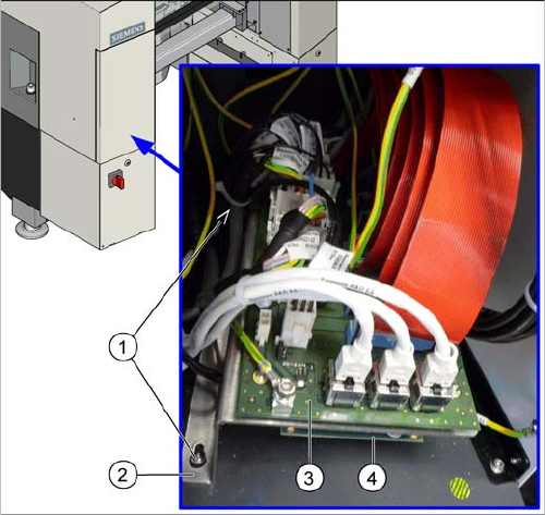
1. Screws fastening the mount
2. Mount
3. Trailing interface
4. Vision hotlink adapter
Service Work Conveyor
3.4.11 Replacing the Trailing Cable Interface [03064127-xx] Gantries
Service Manual SIPLACE SX1/SX2/DX1/DX2 FS02 97
3.4.11
3.4.11 Replacing the Trailing Cable Interface [03064127-xx]
Replacing the Trailing Cable Interface [03064127-xx]
Parts, equipment and tools
▪ Trailing cable interface [03064127-xx]
Overview
Removal
► Switch off the machine, disconnect it from the power supply and secure it to prevent unauthorized
reactivation. Observe the instructions in section "1.2 Preparatory Work..." [ ➙ 13].
► Unplug the electrical connections to the trailing cable interface and the Vision hotlink adapter. Mark
the positions of these connections, to make clear assignment easier later on.
► Loosen the two screws fastening the mount. You can then push the mount backwards and lift it off
the fastening screws.
► Loosen the six screws fastening the trailing cable interface and remove the trailing cable interface
from the mount.
Installation
► Follow the removal instructions in reverse order for installation.
1. Screws fastening the mount
2. Mount
3. Trailing interface
4. Vision hotlink adapter (on the underside of the mount)
The trailing cable interface for gantry 1 is located in sector
1.
The trailing cable interface for gantry 2 ("SX 1 prepared"
and SX2) is located in sector 3.