00192662-01.pdf - 第147页
User Manual SIPLAC E F5/F5 HM 3 Introduction and Basic Concepts Software version SR.407.xx 01/2001 US Edition 3.3 User Interf ace - Views and Menus 147 Cycle mode... Alt+t 3 Y ou use thi s menu i tem to s witch the stati…
3 Introduction and Basic Concepts User Manual SIPLACE F5/F5 HM
3.3 User Interface - Views and Menus Software version SR.407.xx 01/2001 US Edition
146
Software ... 3
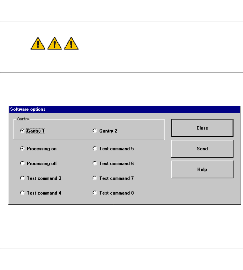
This menu item is used to activate the test commands (test functions) for checking a variety of
machine components. 3
NOTE
This menu item can only be called from the "Service" access level. 3
DANGER
Settings for test commands and test command execution should be performed by service engi-
neers only. 3
Å Click the menu item Software ...
The following window is opened.
3
Å Select the tab corresponding to the required machine component and activate/deactivate the
test commands by clicking the corresponding checkboxes.
Å Click Accept to set the software options.
NOTE
When the station is rebooted, the software options are reset to their original settings. 3
User Manual SIPLACE F5/F5 HM 3 Introduction and Basic Concepts
Software version SR.407.xx 01/2001 US Edition 3.3 User Interface - Views and Menus
147
Cycle mode... Alt+t 3
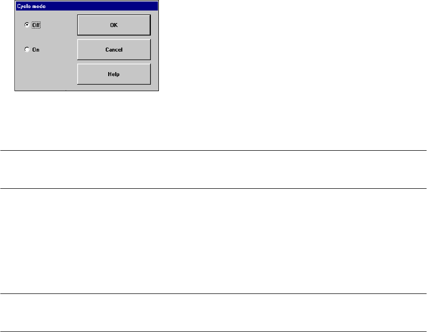
You use this menu item to switch the station to cycle mode (e.g. to localize errors). 3
Å Click the menu item Cycle mode... or press the key combination ALT+t. The "Cycle mode"
settings box is opened.
Å Click the On radio button to activate cycle mode or the Off radio button to deactivate it.
Å Click the OK button. Cycle mode is now either activated or deactivated.
NOTE
In cycle mode, you must press the Start button on the machine for every operating step. 3
Load table program 3
This menu item allows you to reload the table program into the memory of the table program con-
troller. You may need to do this, for example, if a machine error has resulted in the loss of the table
program. 3
NOTE
This function cannot be executed in "Operator" access mode. 3
Å Click the menu item "Load table program".
The program is loaded. (The loading process can take some time).
Video image > Alt+8 3
In the case of certain actions, it may be necessary to display the camera image of the MVS system
on-screen (vision analysis unit) during assembly. 3
Å Click the menu item Video image > or press the key combination ALT+8.
The display area is switched to the MVS system camera image in processing area 1.
Å Press then ESC key to restore the display area to the normal view.

3 Introduction and Basic Concepts User Manual SIPLACE F5/F5 HM
3.3 User Interface - Views and Menus Software version SR.407.xx 01/2001 US Edition
148
Cluster for fine calibration... 3
In the "Stand alone" control mode, you can use this menu item to load the data of a selected clus-
ter (placement program) from the station computer’s hard disk. 3
NOTE
The data for the cluster selected in the box is designed for the assembly of special glass compo-
nents on a glass PCB. The assembled glass PCB is then used for fine calibration in conjunction
with the SITEST test program. 3
Å Click the menu item Cluster for fine calibration...
Å In the box which is now displayed, select the entry corresponding to the required cluster and
click OK to confirm your selection.
The cluster data is now loaded.
GEM-Defaults ... 3
You use this item to specify the GEM parameters which are used as the default parameters when
the station is switched on. 3
Å Click the menu item GEM-Defaults ...
The window in which you set the GEM default parameters is now opened.
For a detailed description, refer to Chapter 12
.
PCB barcode ... 3
You use this item to display a dialog box with a list of the barcodes most recently read by the PCB
barcode reader.
This dialog box also informs you if an error occurred while reading the barcode, if the file format
is incorrect or if no data is available. 3
NOTE
You cannot call the menu item "PCB barcode ..." unless the PCB barcode reader has been in-
stalled in the machine and has been activated in the machine options. 3
Å Click the menu item PCB barcode ...
The "PCB barcode" dialog box is opened.