00192662-01.pdf - 第180页
5 Single Functions User Manual SIPLACE F5/F5 HM 5.2 Single functions, Gantry Software version SR.407.x x 01/2001 US E dition 180 NOTE The revol ver head funct ions can be ex ecuted wit h the ma chine cove r open. T o do …
User Manual SIPLACE F5/F5 HM 5 Single Functions
Software version SR.407.xx 01/2001 US Edition 5.1 General comments
179
5 Single Functions
5.1 General comments
Gantry functions and transport functions are known as single functions. They are used to set up
and test the machines and to carry out particular actions following a machine shutdown caused
by an error.
Single functions can be used to control various function modules in a defined manner.
WARNING
Single functions may only be executed by appropriately qualified and trained personnel, since
improper handling can result in personal injury/damage to the machine.
5.2 Single functions, Gantry
NOTE
The travel functions of the x or y axis can only be carried out when the machine cover is closed.
To execute this function, press the start button.
As a rule, the gantry only travel slowly. 5
5
Å Click on the icon in the toolbar in the Main view (or choose the option SF gantry 1
from the View menu).
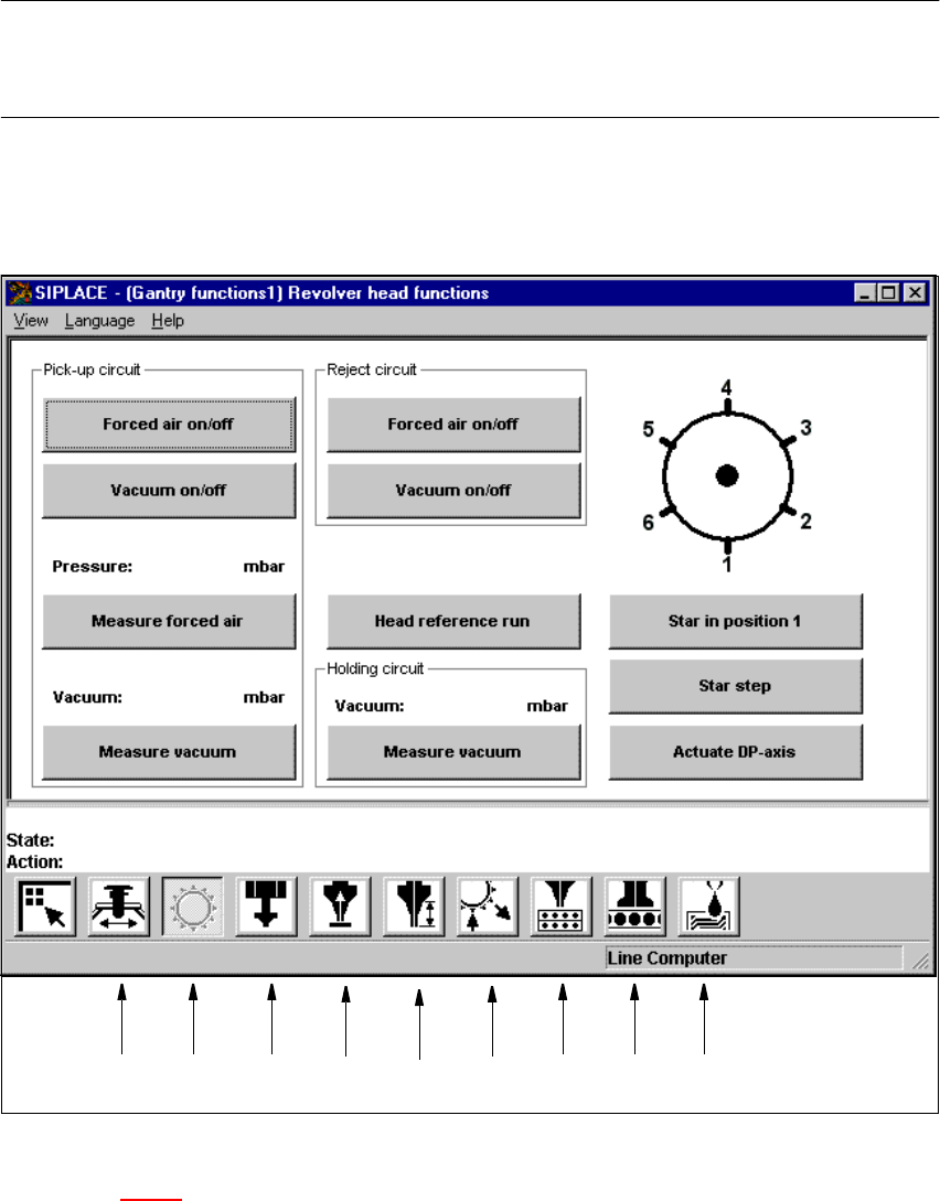
The user interface is switched to the "Revolver head functions" view (see Figs. 5.2 - 1
and
5.2 - 2
).
5
5
5.2.1 "Revolver head functions" screen
The revolver head functions can be used to control all functions relating to the Collect&Place
head. 5
5 Single Functions User Manual SIPLACE F5/F5 HM
5.2 Single functions, Gantry Software version SR.407.xx 01/2001 US Edition
180
NOTE
The revolver head functions can be executed with the machine cover open. To do this the key-
operated switch must be turned to position I. 5
5
5
5
Fig. 5.2 - 1 "Revolver head functions" screen (6-nozzle Collect&Place head)
Key to Fig. 5.2 - 1
(1) Gantry functions
(2) Revolver head functions
(3) IC-head functions
(4) Vacuum test, Collect&Place head
12 34 56789
User Manual SIPLACE F5/F5 HM 5 Single Functions
Software version SR.407.xx 01/2001 US Edition 5.2 Single functions, Gantry
181
(5) Nozzle offset, Collect&Place head
(6) Nozzle configuration, Collect&Place head
(7) Nozzle changer configuration, Collect&Place head
(8) Nozzle changer configuration Pick&Place head
(9) Fluxer head functions
5
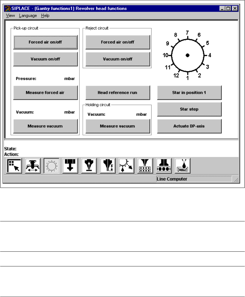
Fig. 5.2 - 2 "Revolver head functions" screen (12-nozzle Collect&Place head)
5
NOTE
Since the functions in the "Revolver head functions" screen are identical for the 6-nozzle and 12-
nozzle Collect&Place heads, they will not be described separately. 5
NOTE
The current position of the Collect&Place head segment is shown by the graphic above the "Star in
position 1" button. 5