00192662-01.pdf - 第194页
5 Single Functions User Manual SIPLACE F5/F5 HM 5.2 Single functions, Gantry Software version SR.407.x x 01/2001 US E dition 194 5.2.5.1 Functions In the "Noz zle o ffset" screen o nly th e "Measu re"…
User Manual SIPLACE F5/F5 HM 5 Single Functions
Software version SR.407.xx 01/2001 US Edition 5.2 Single functions, Gantry
193
5
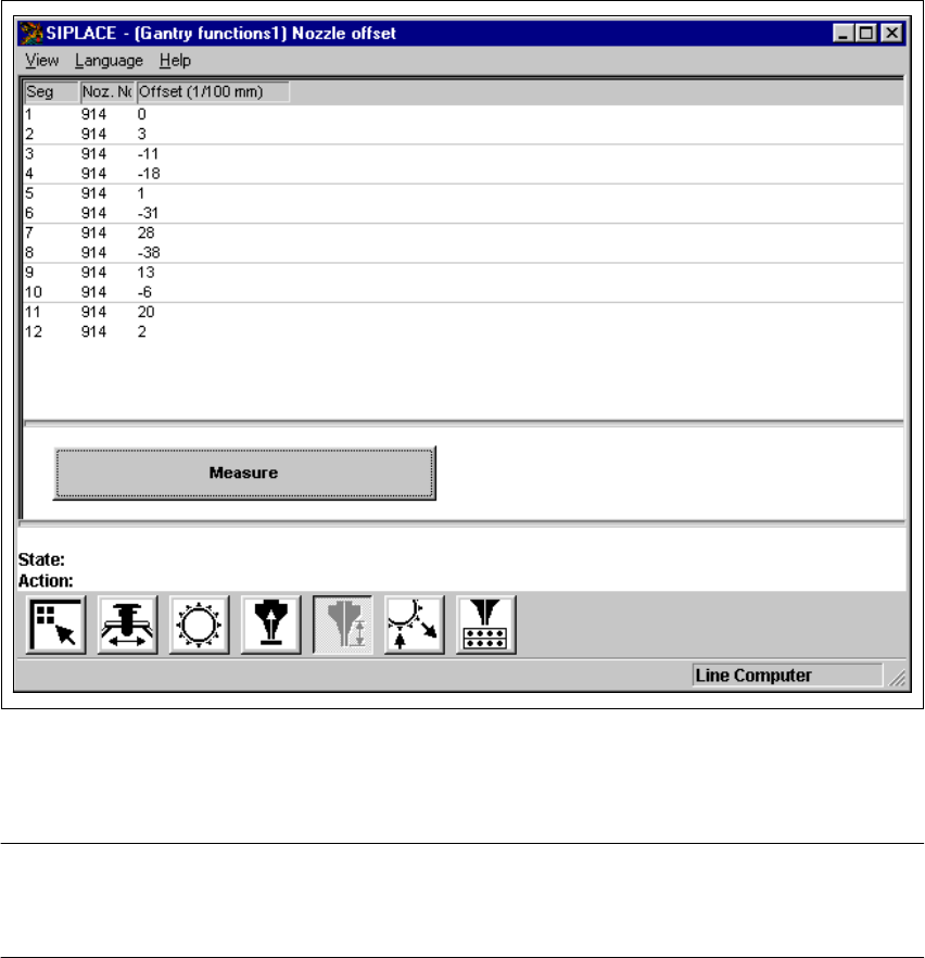
Fig. 5.2 - 8 "Nozzle offset" screen (12-nozzle Collect&Place head)
NOTE
Since the functions in the "Nozzle offset" screen are identical for the 6-nozzle and 12-nozzle Col-
lect&Place heads, they will not be described separately. 5
5 Single Functions User Manual SIPLACE F5/F5 HM
5.2 Single functions, Gantry Software version SR.407.xx 01/2001 US Edition
194
5.2.5.1 Functions
In the "Nozzle offset" screen only the "Measure" button is available. This is used to start a evalu-
ation of the nozzle height for all nozzles.
Measure 5
When this function is activated, after a vacuum check the gantry moves the placement head to a
defined position above the board conveyor. The z-axis is lowered until the nozzle touches the con-
veyor, the procedure is then repeated for each nozzle. In this way, you can measure the height of
each nozzle.
The gantry then returns to its starting position. 5
Å Click the Measure button.
This starts the procedure used to measure nozzle height.
The values determined are displayed in the column "Offset (1/100 mm)" for each of the noz-
zles. These values can, for example, be used to determine whether the nozzle on a particular
segment broken.
User Manual SIPLACE F5/F5 HM 5 Single Functions
Software version SR.407.xx 01/2001 US Edition 5.2 Single functions, Gantry
195
5.2.6 "Nozzle configuration revolver head" screen
5
Å In the current screen for the single functions for Gantry, click the symbol .
The user interface is switched to the "Nozzle configuration revolver head" screen (see
Fig. 5.2 - 9
and 5.2 - 10).
5
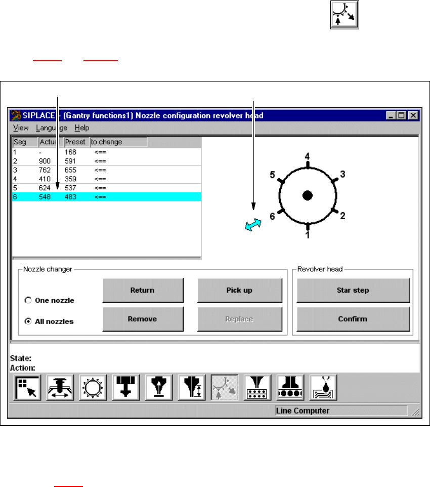
Fig. 5.2 - 9 "Nozzle configuration revolver head" screen (6-nozzle Collect&Place head)
5
Key to Fig. 5.2 - 9
(1) The entry for the segment currently located in the changeover position is highlighted in light
blue.
(2) The arrow points to the number of the segment which is in the changeover position.
5
1
2