00192662-01.pdf - 第220页
5 Single Functions User Manual SIPLACE F5/F5 HM 5.3 Single functions, Transport Software version SR.407.x x 01/2001 US E dition 220

User Manual SIPLACE F5/F5 HM 5 Single Functions
Software version SR.407.xx 01/2001 US Edition 5.3 Single functions, Transport
219
5.3.2.1 General comments
The "PCB conveyor width" screen makes available all functions necessary to adjust the width of
the conveyor.
It may be necessary to change the width of the conveyor, for example, for maintenance work or
when introducing a board with new dimensions. 5
The conveyor can be adjusted to suit the width of the board.
Incremental width adjustments are made by clicking the buttons "Larger" or "Smaller" (see section
5.3.2.2
).
Width adjustments can be made in large increments (increment size = 1 mm) or in smaller steps (in-
crement size = 0,1 mm). This can be controlled by activating or deactivating the "High speed" check
box in the "Width adjustment" area (see section 5.3.2.2
). 5
5
5.3.2.2 Functions
Measure width 5
This function can be used to measure the current width of the conveyor. The result is shown and
saved.
Å Click the Measure width button.
The measured width is displayed above the button.
5
Incremental adjustment
Å Activate the "High speed" check box to adjust the conveyor width in large increments.
Deactivate the check box if you want to adjust the conveyor width in smaller steps.
5
Conveyor width adjustment
Larger 5
Å Click the Larger button to increase the width of the conveyor.
Each time you click the button the width is increased by the increment size set using the
"High speed" check box.
Smaller 5
Å Click the Smaller button to reduce the width of the conveyor.
Each time you click the button the width is reduced by the increment size set using the
"High speed" check box.
5 Single Functions User Manual SIPLACE F5/F5 HM
5.3 Single functions, Transport Software version SR.407.xx 01/2001 US Edition
220
User Manual SIPLACE F5/F5 HM 6 Vision functions
Software version SR.407.xx 01/2001 US Edition 6.1 The vision systems on the placement machine
221
6 Vision functions
6.1 The vision systems on the placement machine
The quality requirements concerning the accuracy of automatic placement systems are constantly
rising, for several reasons: 6
– continuing miniaturization of components,
– increasing lead connection density,
– increasing complexity of PCBs and
– increasing component density.
6
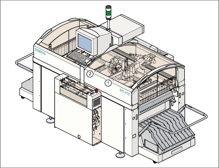
Fig. 6.1 - 1 Position of the placement heads on the machine
(1) Pick&Place head
(2) 6-segment Collect&Place head (F
5
)
6-segment or 12-segment Collect&Place head / DLM1 (F
5
HM)