00192662-01.pdf - 第223页
User Manual SIPLAC E F5/F5 HM 6 Vision functions Software version SR.407.xx 01/2001 US Edition 6.1 The vision systems on the placement machine 223 6 Fig. 6.1 - 2 Component camera system on t he 12-segment Collect&Pla…

6 Vision functions User Manual SIPLACE F5/F5 HM
6.1 The vision systems on the placement machine Software version SR.407.xx 01/2001 US Edition
222
To help meet these requirements, high-precision mechanical components are combined with op-
tical centering and recognition systems (known as vision modules) for components and PCBs. 6
The placement machine has a gantry (see Fig. 6.1 - 1
). The gantry supports: 6
– a 12-segment Collect&Place head (see Fig. 6.1 - 2
) and a Pick&Place head (F
5
machine) or
– a 6-segment or 12-segment Collect&Place head / DLM1 and a Pick&Place head (F
5
HM ma-
chine).
A PCB camera system is mounted on the underside of the head mount (see Fig.
6.1 - 6
). The vision analysis unit plugs into the control unit (see item 1 in Fig. 6.1 - 7). The compo-
nent and PCB cameras and the vision analysis unit together form the vision system. 6
6.1.1 Component vision module on the 12-segment Collect&Place head
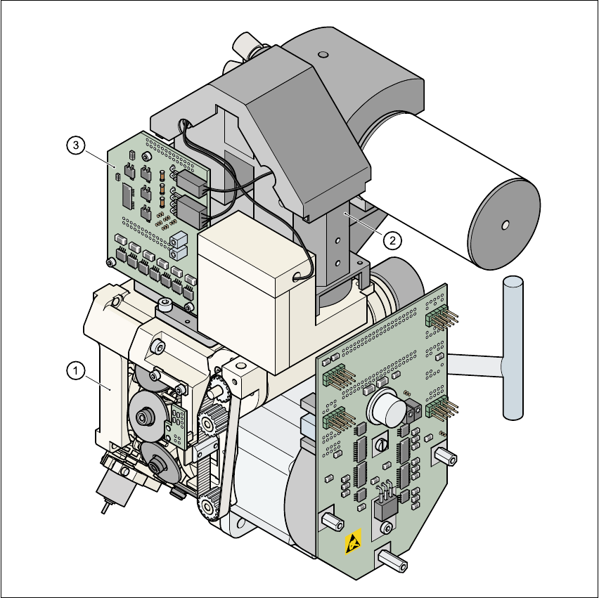
The component vision module (see item 2 in Fig. 6.1 - 2) essentially consists of the following mod-
ules: 6
– Optical lens
– CCD chip for creating an electronic image of the component
– CCD camera amplifier
– Three illumination levels – flat, average and steep – for optimum illumination of a wide
range of component shapes
–“Illumination control” board for setting the intensity of the individual illumination levels.
User Manual SIPLACE F5/F5 HM 6 Vision functions
Software version SR.407.xx 01/2001 US Edition 6.1 The vision systems on the placement machine
223
6
Fig. 6.1 - 2 Component camera system on the 12-segment Collect&Place head
(1) 12-segment Collect&Place head
(2) 24x24 component camera
(3) Component illumination control board
6
The component camera system is fastened to the top of the Collect&Place head using four hexa-
gon socket-head screws. It is then held in place by two parallel pins. 6
The component camera system can be used to optically center and place components ranging
from 0402 up to and including PLCC 44 in size. The components therefore vary in size between
1.0mm x 0.5mm and 18.7mm x 18.7mm, and from 0.3mm and 6mm thick. The minimum lead
pitch can be as little as 0.5mm. 6
6 Vision functions User Manual SIPLACE F5/F5 HM
6.1 The vision systems on the placement machine Software version SR.407.xx 01/2001 US Edition
224
6.1.2 Component vision module on the 6-segment Collect&Place head
(standard vision module)
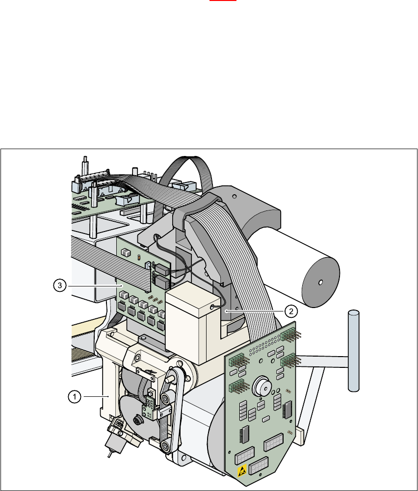
The component vison module (see item 2 in Fig. 6.1 - 6) essentially consists of the following mod-
ules: 6
– Optical lens
– CCD chip for creating an electronic image of the component
– CCD camera amplifier
– Three illumination levels – flat, average and steep – for optimum illumination of a wide
range of component shapes
–“Illumination control” board for setting the intensity of the individual illumination levels.
6
Fig. 6.1 - 3 Component camera system on the 6-segment Collect&Place head
(standard component vision module)
(1) 6-segment Collect&Place head
(2) 24 x 24 component camera
(3) Component illumination control board